
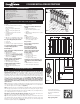
Installation Guide


Step 4 Install decking; notch deck boards to fit around the 4x4 railing posts.
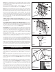
Step 5 Trim 4x4 post sleeves to length. Post sleeves should be a minimum of 1-1/2" lon-
ger than the overall railing height (Figure 4a and 4b). Allow an additional 1-1/2" in your cal-
culation if installing the optional cap rail. Example: For a 36" high railing, trim post sleeve
to a minimum of 37-1/2" (39" with cap rail). Post sleeve can be left longer if desired.
Some wood preservatives may cause an undesirable reaction when directly in contact
with aluminum. The inside of the post sleeve includes a liner to prevent direct contact
with treated structural posts. If your decking is pressure-treated, place shims under the
post sleeve or run a bead of caulk along the bottom edge of the post prior to installing
the post sleeve. This will keep the aluminum from direct contact with the treated decking
and will be concealed by the post base trim. Slide a trimmed post sleeve over each 4x4
railing post. Slide a post base trim over each post sleeve. Add a bead of caulk to the
underside of the post base trim when using treated decking.
Step 6 Measure the distance between installed post sleeves to determine the length of
the top and bottom rails (Figure 1). The distance between the post and first baluster
should be less than 4" and equal on both ends (Figure 4a and 4b). Remove an
additional 1/4" on both ends (1/2" overall) for the bracket to fit between the rail and post.
Trim the top and bottom rails to length.
Angle adaptor wedges are available for 22.5˚ and 45˚ rail angles. Important: the holes
in the angle adaptor wedges line up with the stair rail connectors (sold separately). If
installing a 22.5˚ angle railing, attach the stair connectors and wedges centered on the
posts. If installing a 45˚ angle railing, attach the 45˚ adaptor wedges centered on the
posts. Attach stair connectors to the 45˚ using the provided screws.
Measure the distance between the installed angle connectors to determine the length
of the top and bottom rails. Cut the top and bottom rails to length.
Step 7 Determine the spacing of the balusters.
Classic, Estate and Twist balusters: The rails are pre-drilled with the proper spacing. At-
tach baluster connectors to the top and bottom rails. Do not over-tighten screws.
Apply silicone caulk on each connector to prevent balusters from turning or rattling after
installation is complete. The caulk should be on the outside of the round connector, and
on the inside of the designer baluster connectors. NOTE: Use screws (self tapping) that
are included with rail kit for Classic, Estate and Twist Balusters. DO NOT USE screw
included with baluster connectors.
Ellipse balusters: Both top and bottom rails will be installed with the pre-drilled holes facing
down to prevent water from collecting in the rail. 4-1/4" on-center and equal spacing for
the end spacing. Start by finding the center of the rail. Rail length ÷ 2 = center of rail.
Mark every 4-1/4" from the center line to each end. This will leave the end spacing 4"
or less on both ends and require 24 Ellipse balusters. Attach connectors to both rails
on marked locations. NOTE: Use screws (self tapping) that are included with rail kit for
Classic, Estate and Twist Balusters. DO NOT USE screw included with baluster con-
nectors.
Traditional, Baroque and Arc balusters: Both top and bottom rails will be installed with the
pre-drilled holes facing down to prevent water from collecting in the rail. Maximum 4-1/2"
on-center and equal spacing for the end spacing. Start by finding the center of the rail.
Rail length ÷ 2 = center of rail. Start the first aluminum balusters 2-1/4" on-center each
side of the center line. Mark every 4-1/2" from these lines to each end. This will leave
the end spacing less than 4" on both ends and require 20 aluminum balusters (Figure
5). Tip: Use a piece of 2x4 (3-1/2" actual) as a spacer block for the spacing between
balusters.
Glass balusters: Both top and bottom rails will be installed with the pre-drilled holes facing
down to prevent water from collecting in the rail. 7-1/2" on-center and equal spacing for the
end spacing. Start by finding the center of the rail. Rail length ÷ 2 = center of rail. Start
the first glass baluster 2-1/4" on-center of each side of the center line. Mark every 7-1/2"
from the center line to each end. This will leave the end spacing 4" or less on both ends
and require 12 glass balusters. If installing using connectors, attach connectors to both
rails on marked locations. Tip: If face-mounting to rail, use a piece of 2x4 (3-1/2" actual)
as a spacer block for the spacing between balusters (Figure 5).
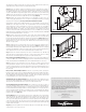
Step 8 Position the bottom rail between posts and center. Check building code
Spacing of 3" is recommended, but can be more or less if codes allow (Figure 4a and 4b).
Mark the location of the bracket on both posts. Remove rail. Mark the screw locations
and pre-drill through the post sleeve only, using a 1/4" drill bit. Attach each bracket to
the post with two 2" long screws.
Step 9 A support block is needed at the center of each rail. Cut the support block to the
proper height. Attach to the bottom of the lower rail (refer to Figure 1). Find the center
of the rail and pre-drill using a 1/8" drill bit. Attach the support block connector using
the included screw. Mark the location of the support block on the deck surface and
attach the other support block connector to the deck using the included screw. Install
the bottom rail between the posts. Using the brackets as a guide, pre-drill each screw
hole using a 1/8" drill bit and attach each end to brackets using two 1" long screws. Tip:
Use a driver extension bit to avoid marring the rail or post sleeve with the drill chuck.
36-
1
/2" Rail
Height
38"
Post
Sleeve
Height
(Rail
Height
plus 1-
1
/2")
32" Baluster
Height
1-
1
/
2
"
Cap Rail
Figure 4a
37-
1
/2" Rail
Height
39"
Post
Sleeve
Height
(Rail
Height
plus 1-
1
/2")
26" Baluster
Height
1-
1
/2"
Cap Rail
Figure 4b
Figure 4c