
Installation Guide
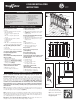

Stair
Bracket (4)
Figure 10
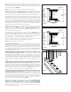
Step 3 Complete stair tread installation prior to installing post sleeves. Trim 4x4
post sleeves to length. If using post caps, post sleeves should be a minimum of
1-1/2" longer than the overall railing height (Figure 4). Allow an additional 1-1/2" in
your calculation if installing the optional cap rail. Example: For a 36" high railing, trim
post sleeve to a minimum of 37-1/2" (39” with cap rail). Post sleeve can be left longer
if desired.
Some wood preservatives may cause an undesirable reaction when directly in con-
tact with aluminum. The inside of the post sleeve includes a liner to prevent direct
contact with treated structural posts. If your decking is pressure-treated, place shims
under the post sleeve or run a bead of caulk along the bottom edge of the post prior
to installing the post sleeve. This will keep the aluminum from direct contact with the
treated decking and will be concealed by the post base trim. Slide a trimmed post
sleeve over each 4x4 railing post. Slide post base trim over each post sleeve. Add
a bead of caulk to the underside of the post base trim when using treated decking.
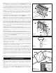
Step 4 Measure the distance between installed post sleeves to determine the length of
the top and bottom rails. Lay bottom rail on stairs with the pre-drilled holes facing down.
The distance between the post and first baluster should be less than 4" and equal
on both ends. Mark the angle and length. Do the same with the top rail. Remove an
additional 1/4" on both ends (1/2" overall) for the bracket to fit between the rail and
post. Trim the top and bottom rails to length with the same angle (Figure 9).
Step 5 Determine the spacing of the balusters, 4-1/2" maximum on-center (7-1/2" on-
center if using glass balusters, 4-1/4" on-center if using Ellipse balusters), and equal
spacing for the end spacing. See Step 7 of the in-line instructions for details.
If using Classic, Estate, Twist or Ellipse balusters, use a 1/8" drill bit to open up the
pre-drilled holes to the angle of the stairs. The top and bottom connectors will be
facing opposite directions. Attach stair baluster connectors to the rails. Do not over-
tighten screws. Apply silicone caulk on each connector to prevent balusters from
turning or rattling after installation is complete. The caulk should be on the outside
of the round connector and on the inside of the designer baluster connector. NOTE:
Use screws (self tapping) that are included with rail kit for Classic, Estate and Twist
Balusters. DO NOT USE screw included with baluster connectors.
Step 6 Position the bottom rail between posts and center. Check building code
requirements for maximum spacing on a staircase, typically less than 6". A 6" ball can-
not pass through the triangle formed by the bottom rail, tread and riser (Figure 10).
Mark the location of the bracket on both posts. Remove rail. Mark the screw locations
and pre-drill through the post sleeve only using a 1/4" drill bit. Attach each bracket to
the post with two 2" long screws.
Step 7 A support block is needed at the center of each rail. Cut the support block to
desired height. Attach to the bottom of the lower rail (refer to Figure 1). Find the center
of the rail and pre-drill using a 1/8" drill bit. Attach the support block connector using
the included screw. Mark the location of the support block on the step tread and at-
tach the other support block connector to the step tread using the included screw.
Step 8 Position the bottom rail between the posts. Pre-drill with a 1/8" drill bit and
attach the rail to the stair brackets using four 1" screws on both ends. Tip: Use a
driver extension bit to avoid marring the rail or post sleeve with the drill chuck.
Classic, Estate, Twist and Ellipse balusters: Attach balusters to the lower rail by slid-
ing onto connectors. NOTE: Use screws (self tapping) that are included with rail kit
for Classic, Estate and Twist Balusters. DO NOT USE screw included with baluster
connectors.
Step 9 Position the top rail between the posts. Check for plumb end-to end-and
vertically. Mark the bracket location on post sleeve and remove rail. Mark the
screw locations using the bracket as a guide, and pre-drill using a 1/4" drill bit through
the post sleeve only. Attach bracket to the post with two 2" long screws at one end.
Repeat for the other end.
Classic, Estate, Twist and Ellipse balusters: Lower the top rail into position, placing the
balusters onto the stair connectors while working from one end of the railing to the
other. Tap with a rubber mallet if needed to eliminate any gaps. Attach the rail to each
bracket by pre-drilling with 1/8" drill bit and using four 1" screws. Tip: Use a driver
extension bit to avoid marring the rail or post sleeve with the drill chuck.
Traditional, Baroque, Arc and Glass balusters: Place the top rail in position. Attach the
rail to each bracket by pre-drilling with a 1/8" drill bit and using four 1" screws. Tip:
Use a driver extension bit to avoid marring the rail or post sleeve with the drill chuck.
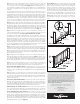
Step 10 Traditional, Baroque and Arc balusters: Place a baluster on the rails on-center
of one of the marked positions (4-1/2" on-center or 7-1/2" on-center for glass). Make
sure the baluster is plumb. Using the baluster as a guide, drill 9/64" holes in the top
and bottom rails. Drill and attach baluster with the screws provided. Use a 2x4 spacer
block to space next baluster. Drill and attach each baluster to the top and bottom
rails with the screws provided. Using a pair of clamps to hold baluster in place while
fastening will make this step easier (Figure 10).
The diagrams and instructions in this brochure are for illustration purposes
only and are not meant to replace a licensed professional. Any construction or
use of the product must be in accordance with all local zoning and/or building
codes. The consumer assumes all risks and liability associated with the
construction or use of this product. The consumer or contractor should take
all necessary steps to ensure the safety of everyone involved in the project,
including, but not limited to, wearing the appropriate safety equipment.
Except as contained in the written limited warranty, the warrantor does not provide
any other warranty, either express or implied, and shall not be liable for any
damages, including consequential damages.
All rights reserved. Deckorators is a registered trademark
of Universal Consumer Products, Inc. in the U.S. 7551-12/15
www.deckorators.com
©2012, 2014 Universal Forest Products
933 US Route 202
Greene, ME 04236-3466
Top and
Bottom Rail
Figure 9
Step 11 (optional) Cut the cap rail and cap rail insert to length
(Note: the cap rail will be 1/2" longer than the top and bottom
rails). Center the cap rail insert on top of the top rail and pre-
drill seven 1/8" pilot holes. Attach the cap rail insert to the top
rail with seven 1/2” long screws. Apply exterior-grade metal
construction adhesive to the mating edges of the insert rail.
Position cap rail over the insert rail. Install by pressing down,
starting from one end and working to the other until the cap
rail snaps into place. Gently tap with a rubber mallet if needed.
Step 12 Apply exterior-grade metal construction adhesive to
the inside edges of the post caps and place over each post
sleeve.