
User Manual

950637-01 15/02/16
Fig.2,1
** (This component may not be included with some models).
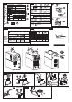
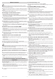
Starting up
Assembly and electrical connections
¾ (Fig.5)
¾
Fig. 3,1.
L
L (Mod.1, Mod.2
Fig.3,4.
¾ 2P+ T per
1Ph) ( 3P+ T per 3Ph)Fig.3,2.
Preparing the welding circuit MMA
¾
¾
L
Preparing the welding circuit TIG
¾
¾
¾ Connect the torch control connector into the connector “R”
¾ “P”
L
Fig. 3,3.
Fig. 6
L
TIG torch (Mod. 3)** cooling system set-up
X
¾
E16
** (This component may not be included with some models).
Welding process: description of controls and signals
¾ “E”
¾ “F”
G
L Table 1
D) Stand By / ON button
Stand By
Stand By
Class A equipment
Welding in conditions of risk
Additional warnings
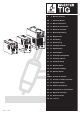
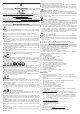
Description of the welding machine
Fig. 1.
Main parts Fig. 1
Stand By
SAVE
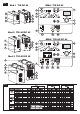
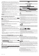
Technical data
Fig. 2
D1D2
1˜
3˜
U0V
I2, U2
X
A/V
U1
I1 eff
I1 max