
User Manual


950628-04 13/11/15
¾ Position (1) on STUDDER
¾ Position (2) on SYNERGIC
¾ (4)
Prg 32 > Prg 36
Prg 37
L
Prg 38
Patching Prg 39
L
L
Spot welder
Fig.6.1, 6.2,
6,3
Prepare the tips correctly
Check tip alignment
¾
Fig.5
Continuous single point spot-welding “Prg 2 > 15”
¾ Position (1) on SPOT WELDER
¾ Position (2) on SYNERGIC
¾ (4)
Pulsating single point spot-welding “Prg 16 > 31” (for sheet metal with a high yield
point or galvanized steel)
¾ Position (1) on SPOT WELDER
¾ Position (2) on SYNERGIC
¾ (4)
L
Test for adjusting spot-welder arms
¾ Position (1) on SPOT WELDER
¾ Position (2) on SYNERGIC
¾ Select the program “PRG 1” (4)
Revision of preset programs
¾ Position (2) on SYNERGIC
¾ (4)
¾ Position (2) on MANUAL
¾
buttons (3, 4)
L
Thermal cutout signal (5)
Maintenance
STUDDER
Torch = check that there are no cuts or abrasions in the cable that bare the internal
SPOT WELDERS
Cables = check that there are no cuts or abrasions in the cable that bare the internal
checks
Extraordinary maintenance
mechanics periodically
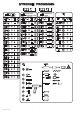
Technical data
Fig. 2
B
U20
I2cc (min imp)
I2cc (max imp)
I2p
U1N
Sp
S50
e
L Arms length
Fmax
Fmin
P1
P2
Mass Weight
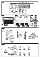
Starting up
Assembly and electrical connections
¾ Fig.8.
¾
TN systems Fig.3
¾
TT systems Fig.3
¾
¾
L
L
L
¾ Plug(2P+T for
1Ph)Fig.3.
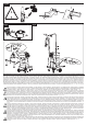
Welding process
FIG.1
Studder: tecnique for use
¾
the
L For repairing doors or cases, it is necessary to connect the copper bar to the part, to