
Owner's Manual


8
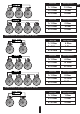
Para ll el c on ne ct io n
SC HE ME S OF E NA BL IN G TH E LO AD O F TH E S U B WO OF ER
Vo ic e co il s 1+ 1, 2 +2 , 4+ 4 Oh m
On e sub wo ofe r, c oi ls i n se ri es
Ω Sub 1 + Ω Sub 2 + Ω S u b 3 . . .
Total impedance=
1
1
1
1
...
...
2+21+1 4+4
The subwoofer has voice coil D1, D2 or D4.
In any case do not expose the amplifier to the loads lower than specified by the manufacturer. Use these schematics to
calculate load impedance of different connection types.
EN
2+2 Ohm
4+4 Ohm
8 Ohm
4 Ohm
1+1 Ohm
2 Ohm
On e su bw oo fe r, c oi ls i n pa ra ll e l
Voice coils
Total impedance
Su bw oo fe rs i n se ri es , co il s in p a r a ll el
2+2 Ohm
4+4 Ohm
2 Ohm
1 Ohm
1+1 Ohm
0.5 Ohm
Voice coils
Total impedance
2+2 Ohm
4+4 Ohm
4 Ohm
2 Ohm
1+1 Ohm
1 Ohm
Voice coils
Total impedance