
Owner's Manual


6
EN
The minimum permissible load impedance at the output of the amplifier is 2 ohm.
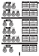
Se ri al c on ne ct io n of t he s pe ak e r s
6. CONNECTION METHODS
In any case do not expose the amplifier to the loads lower than specified by the manufacturer. Use these schematics to
calculate load impedance of different connection types.
4 Ohm
8 Ohm
Voice coil
Total impedance
8 Ohm
16 Ohm
4 Ohm
12 Ohm
Voice coil
Total impedance
8 Ohm
24 Ohm
4 Ohm
16 Ohm
Voice coil
Total impedance
8 Ohm
32 Ohm
1. GND – grounding supply terminal
2. REM IN – connector of remote activation of the amplifier
3. +12V – power supply terminal +12 V
4. FUSE - fuse connection terminal
5. SPEAKERS OUTPUTS – speaker terminal connections
Rem ote c ont ro l
6. POWER – LED for operation (blue)
7. GAIN – input signal level adjustment
6 7