
Owner's Manual


Application of connectors and controls
5
EN
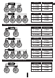
Standard wiring diagram of four-channel amplifier to four speakers
Stan dard wir ing diag ram of fou r-ch ann el am pli fier to he ad u nit
Step 1. Connect the speaker cable from (+) terminal of the amplifier to (+) terminal of the speaker.
Step 2. Connect the speaker cable from (-) terminal of the amplifier to (-) terminal of the speaker.
Step 3. Repeat the installation sequence for each speaker step 1 and step 2
Caution!!! The minimum permissible connection load impedance at single channel is 2 ohm.
For amplifiers MLA-4080, MLA-4120 the operating voltage is 10-15 V.
2 2
2 2
Step 1. Connect one end of the RCA cable to the RCA output terminals at the HU and the second end to the amplifier
RCA inputs terminals marked with CH1/CH2, CH3/CH4.
HPF
1. CROSSOVER – HPF – high pass filter (10 Hz – 12 kHz at 12 dB/Oct)
2. CROSSOVER – selection of built-in filters operating mode (HPF, LPF / BP, FLAT)
3. CROSSOVER – LPF – low pass filter (10 Hz – 12 kHz at 12 dB/Oct)
4. BASS BOOST – bass level adjustment (0/6/12 dB)
5. GAIN – input signal level adjustment 0.2 V – 6 V
6. CH1/CH2, CH3/CH4 – signal input, RCA jacks
7. POWER – LED for operation (blue). PROTECT – LED for operation (red)
8. HI-LEVEL INPUT – high-level signal input (for model MLA-4080)
88