
Owner's Manual


4
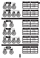
Use the table below to select the desired diameter based
on the length and the current consumption.
Use the table below to select the desired diameter based
on the length and the power consumption.
Selection of the diameter of t h e p o w e r c a b l e s
Selection of the diameter of t h e s p e a ker cab l e s
EN
4. SELECTION OF THE DIAMETER OF POWER CABLES AND SPEAKER CABLES
240-350
180-240
150-180
120-150
100-120
80-100
60-80
40-60
20-40
8-20
0-8
0-1 1-2 2-3 3-4 4-5 5-6 6-7 7-8
53,5
33,6
21,2
8,4
5,3
3,3
2,1
1,3
0,8
1/0
2
4
8
10
12
14
16
18
A.W.G
mm²
Diameter
Cable length (m)
Consumption current (А)
20 000
25 000
15 000
10 000
8000
6000
4000
2000
1000
500
250
100
0-1 1-2 2-3 3-4 4-5 5-6 6-7
Cable length (m)
Power consumption (W)
7-8
16,8
8,37
5,26
2,08
5
8
10
14
A.W.G
mm²
Size
EN
5. WIRING DIAGRAMS
Standard wiring diagram of four-channel amplifier to two speakers, to one subwoofer and to battery
Connect the speaker cables from the positive and negative terminals of the speakers to the respective outputs of the amplifier
terminal marked with CH1 / CH2, CH3 / CH4 SPEAKERS OUTPUTS, as shown at the diagram. To connect the power wire supply it
is necessary to use special power cables. The fuse is placed in the holder and fixed in the cable cut. One end of the cable is
connected to the positive terminal of the battery, the second one – to the amplifier terminals marked with +12V. Be sure to use a
fuse with the parameters sufficient for use in the system. The length and diameter of the grounding cable must conform to the
length and diameter of the cable +12V. Connect one end to the negative terminal of the battery and the other end of the
grounding cable to the terminals marked with GND. Connect the head unit (HU) to low-level inputs of the amplifier using RCA
cable.
Caution!!! The minimum permissible connection load impedance at single channel is 2 ohm.
For amplifiers MLA-4080, MLA-4120 the operating voltage is 10-15 V.
Step 1. Connect the speaker cable from (+) terminal of the amplifier to (+) terminal of the speaker.
Step 2. Connect the speaker cable from (-) terminal of the amplifier to (-) terminal of the speaker.
Step 3. Repeat the installation sequence for each speaker step 1 and step 2
Step 4. Connect the speaker cable from (+) terminal of the amplifier to (+) terminal of the subwoofer.
Step 5. Connect the speaker cable from (-) terminal of the amplifier to (-) terminal of the subwoofer.
Step 6. Connect one end of the power cable from (+) terminal of the battery and the second end to the amplifier terminal marked
with + 12V. Do not forget to protect positive power cable with appropriate fuse.
Step 7. Connect one end of the power cable from (-) terminal of the battery and the second end of the grounding cable to the
terminals marked with GND.
Step 8. Connect one end of the cable to the Remote output terminal at the HU and the second end to the amplifier terminal marked
with REM IN.
4
2 2