
User Manual

IM-pAC Getting Started Guide 61
Issue Number: 5 www.camcoindex.com | www.destaco.com
Read Me First
Instructions
Safety Information Rating Data
Mechanical
Installation
Electrical Installation Keypad and Display
Parameters
Diagnostics
UL Listing
Information
measured, the drive may trip on OV and OI.AC while trying to catch a spinning motor.
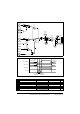
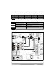
dig: Digital input
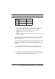
th: Motor thermistor input, connect as per diagram below
Fr: Frequency input.
Fr.hr:High resolution frequency input.
Figure 7-11
Trip resistance: 3kΩ
Reset resistance 1k8
n=0: At zero speed
At.SP: At speed
Lo.SP: At minimum speed
hEAL:Drive ok
Act: Drive active
ALAr: General drive alarm
I.Lt: Current limit active
At.Ld: At 100% load
USEr: User programmable
Fr: Voltage proportional to motor speed
Ld: Voltage proportional to motor load
A: Voltage proportional to output current
Por: Voltage proportional to output power
USEr: User programmable
No Function Range Defaults Type
34
Terminal B7 mode select dig, th, Fr, Fr.hr 0:dig RW
0V
Motor thermistor
input
T1
B7
If Pr 34 is set to th so that terminal B7 is used as a motor thermistor, the functionality of
terminal B7 as set-up with Pr 05, drive configuration, will be disabled.
When setting to th, press mode four times. Analog reference 2 will no longer be selected
as the speed reference. Analog reference 1 should be used.
NOTE
No Function Range Defaults Type
35
Digital output control (terminal B3)
n=0, At.SP, Lo.SP, hEAL,
Act, ALAr, I.Lt, At.Ld, USEr
0:n=0 RW
This parameter is automatically changed by the setting of Pr 12. When Pr 12
automatically controls the setting of this parameter, this parameter cannot be changed.
NOTE
A change to this parameter is only implemented if the drive is disabled, stopped or
tripped and the STOP/RESET key is pressed for 1s.
NOTE
No Function Range Defaults Type
36
Analog output control (terminal B1) Fr, Ld, A, Por, USEr 0:Fr RW
A change to this parameter is only implemented if the drive is disabled, stopped or
tripped and the STOP/RESET key is pressed for 1s.
NOTE