
User Manual


40 IM-pAC Getting Started Guide
www.camcoindex.com | www.destaco.com Issue Number: 5
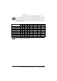
5.2 Ground leakage
The ground leakage current depends upon the internal EMC filter being installed. The
drive is supplied with the filter installed. Instructions for removal of the internal EMC filter
are given in section 5.3.2 Removing the internal EMC filter .
With internal EMC filter installed
30
μ
A DC (10M
Ω
internal bleed resistor, relevant where DC leakage current is being measured)
Size A
1 phase 110V drives
4mA AC at 110V, 50Hz (proportional to supply voltage and frequency)
1 phase 200V drives
10mA AC at 230V, 50Hz (proportional to supply voltage and frequency)
Size B and C
1 phase 200V drives
20mA AC at 230V, 50Hz (proportional to supply voltage and frequency)
3 phase 200V drives
8mA AC at 230V, 50Hz (proportional to supply voltage and frequency)
3 phase 400V drives
8.2mA AC at 415V, 50Hz (proportional to supply voltage and frequency)
Fuses/MCB
The AC supply to the drive must be installed with suitable protection against overload
and short circuits. Failure to observe this requirement will cause risk of fire.
WARNING
The drive must be grounded by a conductor sufficient to carry the prospective fault
current in the event of a fault. See also the warning in section 5.2 Ground leakage
relating to ground leakage current.
WARNING
To avoid a fire hazard and maintain validity of the UL listing, adhere to the specified
tightening torques for the power and ground terminals. Refer to the table below.
WARNING
Frame size Maximum pow er termina l sc re w torque
A 0.5 N m / 4.4 lb in
B and C 1.4 N m / 12.1 lb in
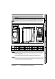
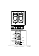
Braking resistor: High temperatures and overload protection
Braking resistors can reach high temperatures. Locate braking resistors so that damage
cannot result. Use cable having insulation capable of withstanding the high temperatures.
It is essential that the braking resistor be protected against overload caused by a failure
of the brake control. Unless the resistor has in-built protection, a circuit like those shown
in
Figure 5-1
and
Figure 5-2
should be used, where the thermal protection device
disconnects the AC supply to the drive. Do not use AC relay contacts directly in series
with the braking resistor circuit, because it carries DC.
WARNING
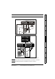
When connecting single phase to a dual rated 200V unit, use terminals L1 and L3.
NOTE
For control terminal connections, see Pr 05 on page 51.
NOTE
For information on the internal EMC filter, see section 5.3.1 Internal EMC filter .
NOTE