
User Manual


IM-pAC Getting Started Guide 37
Issue Number: 5 www.camcoindex.com | www.destaco.com
Read Me First
Instructions
Safety Information Rating Data
Mechanical
Installation
Electrical Installation Keypad and Display Parameters Diagnostics
UL Listing
Information
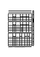
4 Mechanical Installation
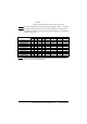
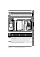
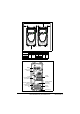
Figure 4-1 IM-pAC dimensions
Mounting holes: 4 x M4 holes
Table 4-1 IM-pAC dimensions
*Size C is not DIN rail mountable.
Enclosure
The drive is intended to be mounted in an enclosure which prevents access except by
trained and authorized personnel, and which prevents the ingress of contamination. It is
designed for use in an environment classified as pollution degree 2 in accordance with
IEC 60664-1. This means that only dry, non-conducting contamination is acceptable.
WARNING
A
B
I
G
D
C
H
E
E
F
G
D
C
Drive
size
ABCDEFGH*I
mm in mm in mm in mm in mm in mm in mm in mm in mm in
A 140 5.51 154 6.06 11 0.43 64 2.52 75 2.95 145 5.71 104 4.09 143 5.63
B 190 7.48 205 8.07 10.9 0.43 65.9 2.6 85 3.35 77 3.0 156 6.15 155.5 6.12 194 7.64
C 240 9.45 258 10.16 10.4 0.41 81.1 3.2 100 3.94 91.9 3.62 173 6.81
244 9.61
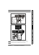
If DIN rail mounting is used in an installation where the drive is to be subjected to shock
or vibration, it is recommended that the bottom mounting screws are used to secure the
drive to the back plate.
If the installation is going to be subjected to heavy shock and vibration, then it is
recommended that the drive is surface mounted rather than DIN rail mounted.
NOTE
The DIN rail mounting mechanism has been designed so no tools are required to install
and remove the drive from a DIN rail. Please ensure the top mounting lugs are located
correctly on the DIN rail before installation is initiated.
NOTE