
User Manual


30 IM-pAC Getting Started Guide
www.camcoindex.com | www.destaco.com Issue Number: 5
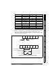
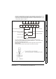
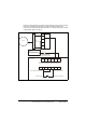
1.28 Drive wiring for a 24Vdc brake motor
Diagram for wiring switches to the IM-pAC control terminals (cover has been removed)
for cycling on demand using a limit switch, momentary start and inverter duty motor.
Index drive is in middle of dwell position see section 1.16 Indexer drive shown in middle
of dwell position diagram on page 10.
1
2
3
4
5
Brake power supply
24Vdc 2.1A
120 - 240 Vac 50 -60 Hz
IMC Pt.No 99A86986000000
White
Red
Blue
BSG Module
+ 24 Vdc
T1 T2 T3 T4 T5 T6
B1 B2 B3 B4 B5
B6
B7
Drive enabled (normally closed)
Momentary Start
Radio Shack Pt.No 275-324
Radio Shack Pt.No 275-609
Limit or proximity switch
for cycling indexer
(open to stop or E-stop)
T5 - T6 build in relay 240 Vac / 30 Vdc - 2A / 6A (resistive)
stop and E-stop switches should have the same rating
Motor
IM-pAC Drive