
User Manual


IM-pAC Getting Started Guide 21
Issue Number: 5 www.camcoindex.com | www.destaco.com
Read Me First
Instructions
Safety Information Rating Data
Mechanical
Installation
Electrical Installation Keypad and Display Parameters Diagnostics
UL Listing
Information
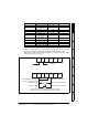
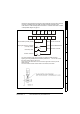
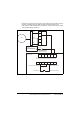
1.23 Drive wiring for a PLC to control speed
Diagram for wiring switches to the IM-pAC control terminals (cover has been removed)
for cycling on demand using a limit switch, momentary start and inverter duty motor.
Index drive is in middle of dwell position see section 1.16 Indexer drive shown in middle
of dwell position diagram on page 10.
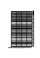
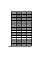
Pr 41 Voltage mode select 2:Fd
Pr 42
Low frequency voltage
boost
4
Pr 43 Serial comms baud rate 19.2
Pr 44 Serial comms address 1
Pr 45 Software version 1.04
Pr 46
Brake release current
threshold
50
Pr 47
Brake apply current
threshold
10
Pr 48 Brake release frequency 1 Hz
Pr 49 Brake apply frequency 2 Hz
Pr 50 Pre-brake release delay 0 s
Pr 51 Post brake release delay 0 s
Parameter Description Value Units
T1 T2 T3 T4 T5 T6
B1 B2 B3 B4 B5 B6 B7
Drive enabled (normally closed)
Stop signal switch on camshaft
(normally closed)
Momentary Start
Radio Shack Pt.No 275-324
IMC Pt.No 87C08062019510
Radio Shack Pt.No 275-609
A project box 5 x 2-1/2 x 2 Radio Shack Pt.No 270-1803
can be used to house the switches and the potentiometer
0
+ 10 Vdc Max