
User Manual

IM-pAC Getting Started Guide 19
Issue Number: 5 www.camcoindex.com | www.destaco.com
Read Me First
Instructions
Safety Information Rating Data
Mechanical
Installation
Electrical Installation Keypad and Display Parameters Diagnostics
UL Listing
Information
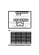
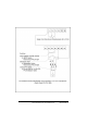
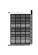
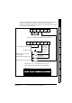
1.21 Drive wiring for using a potentiometer and switch selected
presets to control speed
Diagram for wiring switches to the IM-pAC control terminals (cover has been removed)
for cycling on demand using a limit switch, momentary start and inverter duty motor.
Index drive is in middle of dwell position see section 1.16 Indexer drive shown in middle
of dwell position diagram on page 10.
T1 T2 T3 T4 T5 T6
B1 B2 B3 B4 B5 B6 B7
Drive enabled (normally closed)
Momentary Start
Radio Shack.
Pt.No 275-324
Radio Shack
Pt.No 275-609
Single turn wire-wound potentiometer 2K to 10 K
Ω (
2W)
A project box 5 x 2-1/2 x 2 Radio Shack Pt.No 270-1803
can be used to house the switches and the potentiometer
Reference select 2 B7 SPST switch
Reference select 1 T4 SPST switch
Radio shack
Pt.No 275-324
Radio shack Pt.No 275-324
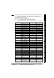
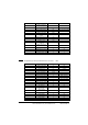
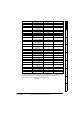
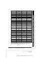
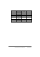
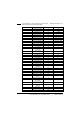
Switch logic
T4
Open
Open
Closed
Closed
B7
Open
Closed
Open
Closed
Reference Selected
Pr A1 speed potentiometer
Pr Preset speed 2
Pr Preset speed 3
Pr Preset speed 4
18
19
20
21
IMC Pt.No
87C08062019510
Stop signal switch on camshaft
(normally closed)