
User Manual

IM-pAC Getting Started Guide 15
Issue Number: 5 www.camcoindex.com | www.destaco.com
Read Me First
Instructions
Safety Information Rating Data
Mechanical
Installation
Electrical Installation Keypad and Display Parameters Diagnostics
UL Listing
Information
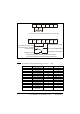
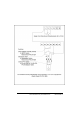
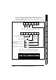
Diagram for wiring switches to the IM-pAC control terminals (cover has been removed)
for cycling on demand using a limit switch, momentary start and inverter duty motor.
Index drive is in middle of dwell position see section 1.16 Indexer drive shown in middle
of dwell position diagram. on page 9.
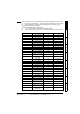
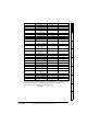
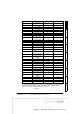
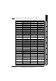
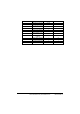
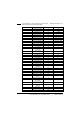
Pr 17
Allow negative
references
OFF
Pr 18 Preset speed 1 0 Hz
Pr 19 Preset speed 2 0 Hz
Pr 20 Preset speed 3 0 Hz
Pr 21 Preset speed 4 0 Hz
Pr 22 Load display units Ld
Pr 23 Speed display units 0:Fr
Pr 24 Customer defined scaling 1
Pr 25 User security code 0
Pr 27
Power-up keypad
reference
0
Pr 28 Parameter cloning 0:no
Pr 29 Load defaults 0:no
Pr 30 Ramp mode select 3:FSt.Hv
Pr 31 Stopping mode select 1
Pr 32 Dynamic V to f select OFF
Pr 33
Catch a spinning motor
select
0
Pr 34 Terminal B7 mode select 0:dig
Pr 35
Digital output control
(terminal B3)
0:n=0
Pr 36
Analog output control
(terminal Bi)
0:Fr
Pr 37
Maximum switching
frequency
12 kHz
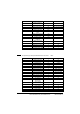
Pr 38 Auto-tune 0
Pr 39 Motor rated frequency - Hz (from motor plate)
Pr 40 Number of motor poles 2:4 pole
Pr 41 Voltage mode select 2:Fd
Pr 42
Low frequency voltage
boost
4
Pr 43 Serial comms baud rate 19.2
Pr 44 Serial comms address 1
Pr 45 Software version 1.04
Pr 46
Brake release current
threshold
50
Pr 47
Brake apply current
threshold
10
Pr 48 Brake release frequency 1 Hz
Pr 49 Brake apply frequency 2 Hz
Pr 50 Pre-brake release delay 0 s
Pr 51 Post brake release delay 0 s
Parameter Description Value Units