INSTALLATION and SERVICE INSTRUCTIONS USE and CARE INSTRUCTIONS BUILT-IN GAS HOB Model: DEGH90WF distributed by DèLonghi Pty Ltd
Dear Customer, Thank you for having purchased and given your preference to our product. The safety precautions and recommendations reported below are for your own safety and that of others. They will also provide a means by which to make full use of the features offered by your appliance. Please keep this booklet in a safe place. It may be useful in future, either to yourself or to others in the event that doubts should arise relating to its operation.
IMPORTANT PRECAUTIONS AND RECOMMENDATIONS FOR USE OF ELECTRICAL APPLIANCES Use of any electrical appliance implies the necessity to follow a series of fundamental rules. In particular: ■ Never touch the appliance with wet hands or feet; ■ do not operate the appliance barefooted; ■ do not allow children or other incapable people to use the appliance without supervision. The manufacturer cannot be held responsible for any damages caused by improper, incorrect or illogical use of the appliance.
INSTALLATION CAUTION: ■ ■ ■ ■ ■ ■ This appliance must be installed in accordance with these installation instructions, local gas fitting regulations, municipal building codes, water supply regulations, electrical wiring regulations, AS5601 / AG 601 - Gas Installations and ony other relevant statutory regulations. This appliance shall only be serviced by authorized personnel. This appliance is to be installed only by an authorised person.
This cooktop has been designed and constructed in accordance with the following codes and specifications: AGA101 (AS 4551) Approval Requirements for Domestic Gas cooking appliances AS/NZS 60335-1 General Requirements for Domestic electrical appliances AS/NZS 60335-2-6 Particular Requirements for Domestic electrical cooking appliances AS/NSZ 1044 Electromagnetic Compatibility Requirements.
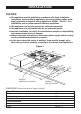
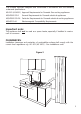
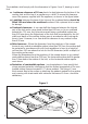
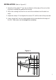
The installation shall comply with the dimensions in Figures 1 and 2, bearing in mind that: ■ A minimum clearance of 20 mm has to be kept between the bottom of the cooking hob and the top of an appliance or a shelf. To ensure this clearance mount the spacers, supplied with the appliance, as shown in the figure below. ■ A partition between the base of the hob and the cupboard below should be fitted 100 mm below the workbench surface if the cupboard is to be used for storage.
INSTALLATION (Refer to Figure 4): 1. Spread out the gasket “C” over the workbench at the edge of the cut out taking care to overlap the gasket at the corners. 2. Slot in the cooking hob into the cut out of the workbench and locate it correctly. 3. Adjust the clamps “A” and tighten the screws “B” until the hob is firmly secured. 4. Using a sharp tool, trim any excess gasket which protrudes from the edge of the hob. Take care not to damage the countertop. Figure 4 C ;;; A 40 mm max. B 20 mm min.
GAS SUPPLY: ■ The connection must be executed by an authorised person according to the relevant standards. ■ Before connecting the appliance to the gas main, mount the brass conical adaptor onto the gas inlet pipe, upon which the gasket has been placed (figures 5a-5b). Conical adaptor and gasket are supplied with the appliance (packed with conversion kit for use with Natural gas or Universal LPG). ■ This appliance is suitable for use with Natural Gas or Universal LPG.
1. After connecting the gas supply, check the piping and connections for leaks using a soap and water solution. The presence of bubbles indicates a leak, tighten or replace connections as appropriate. Warning: Do not use any naked flame to check for leaks. 2. The operation of the appliance MUST be tested before leaving. 3. Adjust the test point pressure or supply pressure to the value which is appropriate for the gas type. 4. Turn on the appliance gas controls and light each burner.
INSTALLATION WITH A FLEXIBLE HOSE ASSEMBLY ■ If this appliance has to be installed with a hose assembly, the installer shall refer to the network operator or gas supplier for confirmation of the gas type, if in doubt. ■ The gas supply connection point shall be accessible when the appliance is installed. ■ Installation with a flexible hose assembly shall be carried out by using a hose with internal diameter of 10 mm minimum. The thread connection shall be Rp 1/2” (ISO 7-1) male.
CONVERSION PROCEDURE (to convert to Natural gas or to ULPG) REPLACING THE INJECTORS The conversion procedure must be carried out only by an authorised person. This appliance is suitable for use with Natural gas or Universal LPG (check the “gas type” sticker attached to the appliance). The nominal gas consumption and injector size details are provided in table at page 10. To replace the injectors proceed as follows: ■ Remove pan supports and burners from the cooktop.
MINIMUM BURNER SETTING ADJUSTMENT Check whether the flame spreads to all burner ports when the burner is lit with the gas tap set to the minimum position. If some ports do not light, increase the minimum gas rate setting. Check whether the burner remains lit even when the gas tap is turned quickly from the maximum to the minimum position. If the burner does not remain lit, increase the minimum gas rate setting. The procedure for adjusting the minimum gas rate setting is described below.
INSTALLATION ELECTRICAL REQUIREMENTS ■ The appliance must be connected to the mains checking that the voltage corresponds to the value given in the rating plate and that the electrical cable sections can withstand the load specified on the plate. ■ The plug must be connected to an earthed socket in compliance with safety standards. ■ If the appliance is supplied without plug, fit a standard plug which is suitable for the power consumed by the appliance.
Replacing the power cord must be done by a qualified electrician in accordance with the instructions supplied by the manufacturer and in compliance with established electrical regulations.
USE and CARE CAUTION: ■ This appliance must be used only for the task it has explicitly been designed for, that is for domestic cooking of foodstuffs. Any other form of usage is to be considered as inappropriate and therefore dangerous. Do not use this appliance as a space heater. ■ Do NOT place combustible materials or products on this appliance at any time. ■ Do NOT spray aerosols in the vicinity of this appliance while it is in use.
GAS HOB ■ Figure 11 14 13 12 11 10 GAS BURNERS 1. 2. 3. 4. 5. Auxiliary burner (A) Triple ring burner (TR) Fish burner (PS) Left semi-rapid burner (SR) Right semi-rapid burner (SR) Natural Gas MJ/h Universal LPG MJ/h 3.6 13.0 10.3 6.3 6.3 3.6 11.9 10.8 6.3 6.3 CONTROL PANEL 10. 11. 12. 13. 14.
USING GAS BURNERS ■ Check that the electricity is switched on to allow spark ignition. ■ Make sure that all controls are turned to zero. ■ The gas flow to the burner is controlled by the knobs on the safety taps. ■ You control the flow by turning the knob indicator to line up with the following symbols: – Symbol : tap closed (burner off) – Symbol : High (maximum) – Symbol : Low (minimum) ■ You can control the temperature by the knob to “High” from “Minimum”.
LIGHTING THE BURNERS (fitted with safety cut-off valve) In order to light the burner, you must: 1 – Turn the knob fig. 12 in anti-clockwise direction up to the maximum aperture (symbol ), push in and hold the knob; this will light the gas. 2 – Wait for about ten seconds after the gas burner has been lit before letting go of the knob (valve activation delay). 3 – Adjust the gas valve to the desired position.
COOKING HINTS FOR GAS HOBS ■ The burner must be chosen according to the diameter of the pans and energy required. ■ For optimum efficiency use a wok or pan no smaller than 230mm diameter.
GRILL FOR SMALL COOKWARE ■ (fig. 14) Put it on the auxiliary burner (the smallest) grid when small cookware is being used to prevent the cookware from tipping over. Figure 14 CORRECT USE OF TRIPLE-RING BURNER ■ The flat-bottomed pans are to be placed directly onto the pan-support. ■ To use the WOK, you must place the wok stand in the CORRECT position as shown in fig. 15. IMPORTANT: The special grille for wok pans (fig. 15) MUST BE PLACED ONLY over the pan-rest for the triple-ring burner.
Cleaning and Maintenance GENERAL TIPS ■ ■ ■ ■ ■ Before cleaning the hob switch it off and wait for it to cool down. Clean with a cloth, hot water and soap or liquid detergent. Do not use products which are abrasive, corrosive or chlorine based. Do not use steel pads. Do not leave acid or alkaline substances (vinegar, salt, lemon juice, etc.) on the hob. ENAMELLED PARTS ■ ■ All the enamelled parts must be washed only with a sponge with soapy water or other non-abrasive products.
GAS TAPS ■ ■ Regular lubrication of the gas taps must only be performed by Authorized person. If the gas taps are not working properly, call our Customer Service Centre to obtain the nearest Authorized Delonghi Service Agent. CORRECT POSITIONING OF THE BURNERS ■ ■ ■ ■ ■ It is very important to check that spreader “F” and cap “C” of the burner (see Figures 16 and 17) are perfectly in place because if they move out of place serious problems could arise. Make sure that electrode "S" (Fig.
CORRECT POSITIONING OF THE TRIPLE-RING BURNER ■ The triple ring burner must be correctly positioned (see fig. 20); the burner rib must be located in position as shown by the arrow (see fig. 18). ■ The burner correctly positioned must not rotate (fig. 19). ■ Then position the cap “A” and the ring “B” (fig. 19).
CORRECT POSITIONING OF THE FISH BURNER ■ This burner must be correctly positioned as shown in the figure 21. ■ Check that the electrode “S” (fig. 21) is always clean to ensure trouble-free sparking. ■ Check that the probe “T” (fig. 21) next to the burners is always clean to ensure correct operation of the safety valve. ■ Both the probe and ignition plug must be very carefully cleaned.
SERVICE AND MAINTENANCE If the ignition spark fails to ignite or does not light the gas, check the following items before calling our Customer Service Centre to obtain the nearest Authorised Delonghi Service Agent: ■ ■ ■ Burner is reassembled and located correctly. Spark electrode and white ceramic are clean and dry. 240 VAC power supply is connected. Contact the local gas utility or our Customer Service Centre to obtain the nearest Authorized Delonghi Service Agent.
Descriptions and illustrations in this booklet are given as simply indicative. The manufacturer reserves the right, considering the characteristics of the models described here, at any time and without notice, to make eventual necessary modifications for their construction or for commercial needs.
Cod.