
Operation Manual

68
71.06953.01 - EN
INSTALLATION INSTRUCTIONS
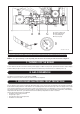
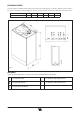
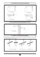
14. DIMENSIONI CALDAIA 15. DIMENSIONS OF BOILER
Figure 5
24 BIC FF 24 BIC
CG_1848 / 1104_0702
CG_1848 / 1104_0703
16. INSTALLING THE FLUE AND AIR DUCTS
If fumes are discharged outside the building, the ue-air duct must protrude
at least 18 mm from the wall to allow an aluminium weathering surround to be
tted and sealed to avoid water inltrations.
Make sure there is a minimum upward slope towards the outside of 1 cm per
metre of duct.
•
A 90° curve reduces total duct length by 1 metre.
•
A 45° curve reduces total duct length by 0.5 metres.
The first 90° curve is not considered when calculating the maximum avai-
lable length.
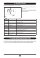
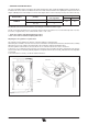
Figure 7
Connector
0805_2901 / CG_2073
Model 24 BIC FF
The boiler is easy and exible to install thanks to the extensive range of available
accessories, as described below.
The boiler has been designed for connection to a vertical or horizontal coaxial
ue-air duct. A splitting kit is also available if separate ducts are required.
Only accessories supplied by the manufacturer must be used for installation!
WARNING: To optimise operating safety, make sure the flue ducts are firmly
fixed to the wall with suitable brackets.
… COAXIAL FLUE-AIR DUCT (CONCENTRIC)
This type of duct is used to discharge exhaust fumes and draw combustion air
both outside the building and if a LAS ue is tted.
The 90° coaxial curve allows the boiler to be connected to a ue-air duct in any
direction as it can be rotated by 360°. It can also be used as a supplementary
curve combined with a coaxial duct or a 45° curve.
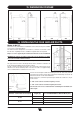
Figure 6
Diameter coaxial flue-air duct (mm) Lenght (m)
Use of DIAPHRAGM on INLET LINE A (mm)
60/100
0 ÷ 1,5 Ø 76
1,5 ÷ 4 NO
80/125
0 ÷ 5 Ø 80
5 ÷ 10 NO