
Operation Manual

44
GT 530A DDR_G30A/AE _IO_V4.0 09/2013
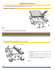
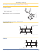
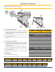
36. Installing the cable channels (FA16 To FA24)
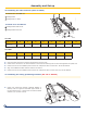
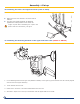
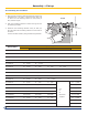
37. Installing the casing positioning brackets (MA 245 or MA246)
1
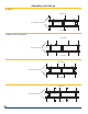
Package FA16
2
Package FA17 to FA24
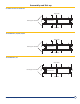
1
Package FA18-FA24-Mount
2
Package FA24-Reversed
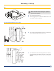
GT 530A
Number of sections 18 19 20 21 22 23 24 25
Length(in/mm) 98.87”/2,510 102
.
37”/2,600 110.25”/2,800 114.25”/2,910 118
.
12”/3,000 122
.
43”/3,110 126”/3,200 130.31
”
/3,310
GT 530AE
Number of sections 26 27 28 29 30 31 32
Length(in/mm)
134.6/3420 138.9/3530 143.3/3640 147.6/3750 151.9/3860 156.2/3970
160.6/4080
Place the cable channels so that their bevelled end is to the front.
Fasten with 2 screws H8 x 16 and L8 washers in the third hole starting from the front and opposite the special nut.
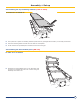
Fasten them to the intermediate piece and the rear crosspieces with 2 screws H8 x 16 and L8 washers.
Align the 2 additional cable channels with the two others.
Fasten them to the intermediate piece and the rear crosspieces with 4 screws (H8 x 16) and L8 washers.
A
Front
1
2
Fasten the positioning brackets (package MR245 or
MR226) onto the right and left-hand upper bosses of
the front section with : 2 screws H8 x 16 and 2 serrated
washers (1/2” /13mm wrench).
Assembly and Set up
GT 530A-18 to Gt 530A-25
GT 530Ae-26 to Gt 530Ae-32