
Operation Manual

42
GT 530A DDR_G30A/AE _IO_V4.0 09/2013
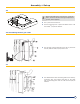
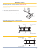
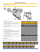
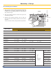
32. Installing the top insulating material (FA30 to FA36)
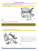
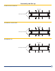
33. Installing the cable channels (FA16 to FA27)
2
Front
Put in place the 23
5/8”
600mm mm wide (packages FA35
to FA36) top insulating material on the body of the boiler
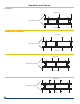
Number of section GT 530A-15+16 GT 530A-17
Length (mm) 82
11/16”
/ 2,100 86
5/8
/2,200
2
3
1/2
/80mm
3
1/2”
/90mm
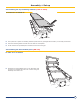
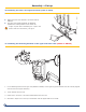
Place the cable channels so that their bevelled end is at
the front.
Fasten with 2 screws H8 x 16 and L8 washers in the
third hole starting from the front and opposite the
special nut.
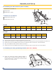
Fasten at the rear with 2 screws H8 x 16 and L8 washers
opposite the oblong holes and special nut.
1
Rear
AVANT
Assembly and Set up
GT 530A-15 to Gt 530A-17