
Operation Manual


26
GT 530A DDR_G30A/AE _IO_V4.0 09/2013
Assembly + Set up
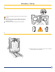
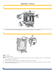
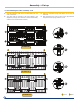
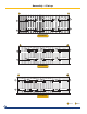
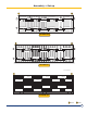
12. Assembling the side assembly rods
The side assembly rods must be assembled from the
rear to the front.
The rods must be inserted in the holes stated in the
diagrams (the lugs of the sections in which the assembly
rods are to be inserted have 2 holes).
B
B
B
B
E
E
E
E
C
C
C
C
C
C
C
C
D
D
D
D
D
D
D
D
GT 530A-16
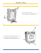
B
B
B
B
E
E
E
E
C
C
C
C
C
C
C
C
D
D
D
D
D
D
D
D
GT 530A-17
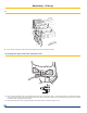
F1
F1
F1
R2
R2
R2
GT 530A-15
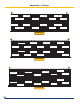
Place the expansion spring and washer on the rear of
each rod.
Stop tightening the nuts as soon as the gap between
the spires of the springs is about 1 mm
20
1/2”
/520mm
20
1/2”
/520mm
20
1/2”
/520mm
16
1/2”
/420mm
16
1/2”
/420mm
20
1/2”
/520mm
20
1/2”
/520mm
20
1/2”
/520mm
20
1/2”
/520mm
20
1/2”
/520mm
20
1/2”
/520mm
20
1/2”
/520mm
20
1/2”
/520mm
20
1/2”
/520mm
20
1/2”
/520mm
20
1/2”
/520mm
16
1/2”
/420mm
16
1/2”
/420mm
16
1/2”
/420mm 16
1/2”
/420mm
16
1/2”
/420mm
16
1/2”
/420mm
16
1/2”
/420mm
16
1/2”
/420mm
16
1/2”
/420mm
16
1/2”
/420mm
F1 R2
RearFront
15
3/16”
/385mm