
Operation Manual


22
GT 530A DDR_G30A/AE _IO_V4.0 09/2013
5
4”/100mm
4”/100mm
4”/100mm
4”/100mm
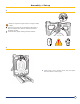
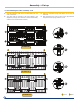
Fill the bottom of the W groove opposite the U groove for the intermediary parts (located on the periphery of the section)
with a continuous bead of DOW CORNING silicone, approximately Ø
3
/16” / 5 mm diameter.
6
1
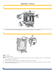
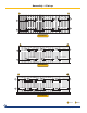
Rear section
2
Intermediate section
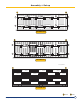
Place the rst normal intermediate section, making sure that it is turned in the right direction, i.e. with the attening
groove against the thermocord.
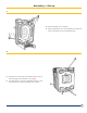
For safety, insert a lateral assembly rod (supplied) in the holes of the 2 sections.
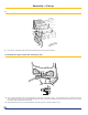
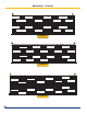
Push the section gently and simultaneously on to the 2 nipples of the rear section with a hammer and a piece of wood
positioned in line with the bores.
Assembly + Set up
2
1