
Operation Manual


13
GT 530ADDR_G30A/AE _IO_V4.0 09/2013
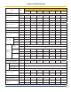
Clearances
The GT 530A/AE boiler has a sturdy underframe,
it does not need any special base although a house
keeping pad is recommended to keep steel parts out
of casual water. Its combustion chamber is closed, so
it is not necessary to place it on a reproof oor, but
the oor must be able to bear the weight of the boiler
subject to state and local code NFPA 31 and state Fire
Marshall.
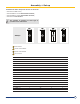
The minimum dimensions shown on the following
drawing are provided as recommendations and
guidelines for service access.
If A= 47
1/4”
(side burner side door open),
A’=47
1/4”
(side burner door open): dimensions to be
adopted according to the space required for the burner
when the door is open.
Dimensions “X” = burner length plus 24 inches for
service
Ref.
GT 530A GT 530AE
-15 -16 -17 -18 -19 -20 -21 -22 -23 -24 -25 -26 -27 -28 -29 -30 -31 32
C min
In
5.9 5.9 14.57 14.57 14.57 25.59 25.59 25.59 38.58 38.58 38.58
60 57.4 56.5 57.4 53.8 55.4 54.7
mm
150 150 370 370 370 650 650 650 980 980 980
1,524 1,457.9 1,435.1 1458 1,366.5 1407.1 1389.3
E
In
61.68 61.68 61.68 61.68 61.68 61.68 61.68 61.68 61.68 61.68 61.68 64.68 64.68 64.68 64.68 64.68 64.68 64.68
mm
1566.6 1566.6 1566.6 1566.6 1566.6 1566.6 1566.6 1566.6 1566.6 1566.6 1566.6 1,642.9 1,642.9 1,642.9 1,642.9 1,642.9 1,642.9 1,642.9
L
In
88.37" 92.68" 96.18" 100.62” 104.12” 112
”
116.31” 119.87” 124.25” 127.75” 132.12” 135.62 143.50 146.6 151.37 159.25 163.58 164.17
mm
224.4 235.40 244.29 255.57 264.46 284.48 295.42 304.46 315.59 324.48 335.58 3445 3645 3755 3845 4045 4155 4170
M
In
12.75” 10.62” 12.62” 10.43” 11.31” 10.62” 12.75” 10.62” 12.75” 9.87” 11.87” 11.57 15.1 15.03 14.21 17.71 17.67 16.85
mm
323.8 269.7 320.5 264.9 287.2 269.7 323.8 269.7 323.8 250.6 301.4 294 383 382 361 450 449 428
Installation Specication
CAUTION
Do not install boiler on combustible ooring or carpet.
Clearance shown are to combustible materials and ser-
vicing.
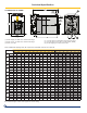
X
L
M
C
A”
A
E
33
1/2”
46
3/16”
11
1
/
1
6”
300mm