Oil/Gas-Fired Near-Condensing Hot Water Boiler De Dietrich GT 530A and GT530AE Series Assembly, Installation and Service Manual Product may not be exactly as shown. www.dedietrichboilers.com DDR_G30A/AE _ISM_V4.
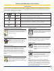
Safety and Warranty Information Symbols used Read this manual carefully before installing the boiler or putting it into operation. This manual must be retained for future reference. If the information in this manual is not followed exactly, a fire or explosion may result causing property/product damage, serious personal injury and possibly death. Make sure all the requirements detailed in this manual are understood and completed.
Safety Information Operation Before operating the boiler, make sure you fully understand its method of operation. Your heating contractor should always perform the initial start-up and explain the system. Any warranty is null and void if these Flue gas smell • • • • • • • • • Deactivate heating equipment. Open windows and doors. Do not try to light any appliances. Do not touch any electrical switches, do not use any phone in your building.
Safety Information and Codes Codes CAUTION The operator/ultimate owner is required to have the heating boiler, burners, and controls checked, as a minimum once per year, by the original installer or by a competent heating contractor familiar with the equipment. Defects must be corrected immediately. Do not use this boiler if any part has been under water.
Safety Information and Codes Water pipe freezing hazard Combustion sources and ventilation air contaminants WARNING Serious property damage and/or personal injury can occur if the pipes are not protected from freezing resulting in the pipes bursting. The boiler may also shut down. Turn off the water supply and drain the water pipes or protect them from freezing when leaving the home unattended for long periods of time during very cold weather conditions.
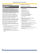
General Information Control panel designed to enable easy wiring connections Sensor well Eutectic® cast iron boiler body, thermal shock and corrosion resistant,allowing low modulated temperature operation and complete stop between heating periods Large wiring duct leading to the control panel Flue nozzle with two cleaning traps directly accessible without dismantling the castings Silicone wrapped ceramic thermocord assures flue gas tightness Hinged cleaning door (right hand or left hand side) 4 access
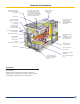
Technical Specifications Boiler Model Gt 530A Series Item Unit -15 -16 -17 -18 Firing Sequence -19 -20 -21 -22 -23 -24 -25 Sonsult Burner Technical Data MBH 3,749 3,966 4,254 4,470 4,759 4,975 5,191 5,480 5,696 5,984 6,201 kW 1,099 1,162 1,274 1,310 1,395 1,458 1,521 1,606 1,669 1,754 1,817 USGPH 26.00 27.50 29.50 31.00 33.00 34.50 36.00 38.00 39.50 41.50 43.00 MBH 3.194 3.379 3.624 3.809 4.054 4.239 4.423 4.669 4.853 5.099 5.283 kW 936.2 990.
Technical Specifications Boiler Model Gt 530AE Series Item Unit -26 -27 Firing Sequence -28 -29 -30 -31 -32 Sonsult Burner Technical Data MBH 6,483 6,652 6,825 7,166 7,505 7,849 8,190 kW 1,900 1,950 2,000 2,100 2,200 2,300 2,400 US GPH 43.8 45.8 47.7 49.7 51.6 53.6 55.5 MBH 5,524 5,668 5,815 6,105 6,394 6,687 6,978 kW 1,618.8 1,661.1 1,704.2 1,789.4 1,874.1 1,959.9 2,045.
Technical Specification GT 530A and GT 530AE 6 4 5 R (1) Boiler Supply 5” ANSI 150# welded neck flange (2) Boiler return, 5” ANSI 150# welded neck flange (3) Drain, 3/4” NPT (4) 1/2” NPT port for temperature and pressure gauge (5) 3/4” NPT port for low water cut-off control (LWCO) (6) 2# NPT tapping for safety Relief valve.
Installation Specification Clearances CAUTION The GT 530A/AE boiler has a sturdy underframe, it does not need any special base although a house keeping pad is recommended to keep steel parts out of casual water. Its combustion chamber is closed, so it is not necessary to place it on a fireproof floor, but the floor must be able to bear the weight of the boiler subject to state and local code NFPA 31 and state Fire Marshall.
Installation Specification Combustion Air Requirements WARNING • • • • • • Inadequate combustion air supply will result in carbon monoxide [CO] development Ensure boiler room is provided with an obstruction free combustion air sources. Sources must be sized to provide ample supply, more than one opening maybe required.
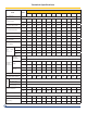
Installation Specifications Piping D 421/2” c water supply flange: 5” Water return flange : 5” B 8” 7/ 7 GT530A GT530AE -15 -16 -17 -18 -19 -20 -21 -22 -23 -24 -25 -26 -27 -28 -29 -30 -31 -32 B -1.22" -1.18" -0.354" -0.315" 0.512" -1.417" -1.378" -0.551" -0.512" 0.315" 0.354" 1.02" -2.48" -2.44" -1.61" -5.11" -5.07" -4.25" -31 -30 -9 -8 13 -36 -35 -14 -13 8 9 26 -63 -62 -41 -130 -129 -108 C 58.58" 58.58" 58.58" 59.2" 59.2" 59.2" 59.
Installation Specifications Recommendations • • • • The installation must be made in accordance with codes in effect. An expansion tank has to be connected to the system Safety valve must be connected to the boiler piping without any valve or stop installed between the device and the boiler. Pressure reducing valve and back flow preventer on boiler make up water feed.
Installation Specifications Replacement ______________________procedures __________________________________________________________________________________________________________________________________ • When an existing boiler is removed from a common and bathroom exhausts, so they will operate at venting system, the common venting system is the maximum speed. Do not operate a summer likely to be too large for proper venting of the exhaust fan. Close fire place dampers.
Installation Specifications Dimensional information required the boiler ______________________ ____________________ ______________for ______connection ___________________of _____ ______ ______________________________________________________________ L K 2” 3 3/ 23 ” 32 3/ 23 GT530A -15 K L 18 GT530A -16 -17 -18 -19 -20 -.74” -.70" 0.12” .15" .98” -.94” mm -19.0 -18.0 3.0 4 25 -24 -23 -2 -1 20 In -21 -22 -23 -24 -0.90” -0.07” -.032" 0.
Assembly + Set up Assemble the boiler body from the rear to the front : - assemble the rear section, - assemble all the normal intermediate sections, - assemble all the special intermediate sections, - assemble the front section.
Assembly + Set up 1 1 2 1 Boilers : 14, 16, 18, 20, 22, 24 sections 2 Boilers : 15, 17, 19, 21, 23, 25,26, 27,28, 29,30, 31,32, 33 sections Establish the location of the frame on the basis of the opening direction of the boiler door and the length of the burner. Leave enough clearance at the rear of the boiler for water connections and the distributing tube. Fit the rear section on the frame, behind the fastening brackets (see detailed drawing) and prop it up.
Assembly + Set up 3 Handle the nipples with gloves as there might be sharp edges. Remove any traces of rust protective paint with a fine to medium wire wheel so that the surface is perfectly smooth. Coat with the nipple coating with the sections. 4 Gently push in the 2 nipples. Ensure they are square and not pushed in at any angle. A R R IÈ R RR E A E RE D IÈ S S U S - S E B ES O D N - U T S O - P O B V N A E A N -T T O P AV A N T DDR_G30A/AE _IO_V4.
Assembly + Set up 5 4”/100mm 4”/100mm 4”/100mm 4”/100mm Fill the bottom of the W groove opposite the U groove for the intermediary parts (located on the periphery of the section) with a continuous bead of DOW CORNING silicone, approximately Ø 3/16” / 5 mm diameter. 6 1 2 1 Rear section 2 Intermediate section Place the first normal intermediate section, making sure that it is turned in the right direction, i.e. with the flattening groove against the thermocord.
Assembly + Set up 7 Put the assembly tool in position. Tighten gradually so as to bring together the upper and lower connections evenly and simultaneously. 8 Assemble the remaining intermediate sections one by one according to the procedure in step 3-10 First assemble the normal intermediate sections, then the special ones. Leave the assembly tool in place. DDR_G30A/AE _IO_V4.
Assembly + Set up 9 Trim off any projecting ends of the thermocords flush with the coast sections. 10. Fitting the upper and lower assembly rods On the lower assembly rods, fit the following at each end in the given order : an expansion spring, a washer and a nut (the holes of the front lugs must be aligned with the holes of the frame brackets as the assembly rods are used to make the boiler body integral with the frame).
Assembly + Set up 11 R1 R1 Rear F2 Front F2 Put in place the upper assembly rods in the two front and rear lugs. For 26-32 sections boilers, the provided extension and coupling will be required. Mount the 2 crosspieces (supplied in package MR245/246) with their bends turned backwards and fasten them to the rods with an expansion spring, 1 nut and 1 washer Remove the assembly tool. DDR_G30A/AE _IO_V4.
Assembly + Set up 12. Assembling the side assembly rods The side assembly rods must be assembled from the rear to the front. Place the expansion spring and washer on the rear of each rod. The rods must be inserted in the holes stated in the diagrams (the lugs of the sections in which the assembly rods are to be inserted have 2 holes).
Assembly + Set up B A EA D C 1 1 1 1 R1 F2 C 201/2” /520mm E D E D 161/2” /420mm C 201/2” /520mm D 161/2” C 201/2” /520mm B 161/2” /420mm C 201/2” /520mm D /420mm 201/2” /520mm 161/2” 201/2” /520mm B /420mm GT 530A-18 R1 F2 C 201/2” /520mm E D E D 201/2” D 201/2” C B 201/2” /520mm B C D /520mm B 161/2” /420mm 201/2” /520mm C D E D C 201/2” /520mm C D /520mm 201/2” /520mm E C 201/2” /520mm C D 161/2” B /420mm GT 530A-19 R1 F2 C A A C
Assembly + Set up R1 F2 201/2” /520mm C A 161/2” 201/2” /520mm C A 161/2” 201/2” /420mm C D /420mm 153/16” C 201/2” /520mm 201/2” /520mm B /385mm C D 153/16” /520mm C D /520mm D 201/2” 201/2” /520mm 201/2” /520mm B /385mm GT 530A-21 R1 F2 201/2” /520mm C A D 201/2” /520mm C E D 201/2” /520mm C A E 201/2” /520mm C D C R1 C D C 161/2” /420mm 161/2” /420mm C D 161/2” /420mm D D 201/2” /520mm GT 530A-22 161/2” C D D 161/2” /420mm /420mm D C 2
Assembly + Set up R1 E F2 C 161/2” /420mm D E D 161/2” /420mm 161/2” /420mm D E C 201/2” /520mm C D C C /520mm C D C 161/2” /420mm D 201/2” 201/2” /520mm D D D E C 201/2” /520mm C D C D B B 153/16” /385mm C 201/2” /520mm 201/2” /520mm 201/2” /520mm 201/2” /520mm B C 153/16” /385mm B D GT 530A-24 R1 E 161/2” E F2 D E E C D /420mm C C D C 201/2” /520mm C D /520mm C D 201/2” /520mm 161/2” /420mm D 201/2” 201/2” 201/2” D 201/2” /520mm C
Assembly + Set up R1 F2 123/5” /320mm 201/2” /520mm 201/2” /520mm 161/2” /420mm 201/2” /520mm 123/5” /420mm 153/16” /385mm 201/2” /520mm 201/2” /520mm 153/16” /385mm 201/2” /520mm 201/2” /520mm 201/2” /520mm 161/2” /420mm 201/2” /520mm 201/2” /520mm GT 530-27 GT 530AE-27 R1 F2 161/2” /420mm 161/2” /420mm 161/2” /420mm 161/2” /420mm 161/2” /420mm 161/2” /420mm 161/2” /420mm 201/2” /520mm 161/2” /420mm 161/2” /420mm 161/2” /420mm 153/16” /385mm 201/2” /520mm 161/2” /420mm 16
Assembly + Set up R1 F2 153/16” /385mm 201/2” /520mm 201/2” /520mm 201/2” /520mm 201/2” /520mm 201/2” /520mm 201/2” /520mm 201/2” /520mm 153/16” /385mm 201/2” /520mm 201/2” /520mm 201/2” /520mm 201/2” /520mm 201/2” /520mm 201/2” /520mm 201/2” /520mm GT 530-30 GT 530AE-30 R1 F2 153/16” /385mm 161/2” 201/2” /420mm 161/2” /420mm 201/2” /520mm 201/2” 161/2” /420mm /520mm 201/2” /520mm /520mm 201/2” /520mm 153/16” /385mm 161/2” 201/2” /420mm 161/2” /420mm 201/2” /520mm 201/2”
Assembly + Set up 13. Assembling the pocket and the plugs GT 530A 15-19 A Front GT 530A 20-32 B Assemble the well for the thermostats and thermometer in : The third special intermediate section -515/16” /151mm wide, 1/2’’ hole for GT 530A-15 to GT 530A-19 or the fourth special intermediate section - 515/16” /151mm wide, 1/2’’ hole for GT 530A-20 to GT 530AE-32.
Assembly + Set up 14. Hydrostatic Test 1 After assembling the boiler body, the installer must carry out a water tightness test at a pressure equal to 1.5 times the operating pressure (that is 135 Psig Max. of 145) a minimum 20 minutes. The test must be done at room temperature with a city water tempreature not less than 60°f/15°C. Fit a square flange with hole facing upwards onto the upper flange with outlet piece. Fit a blind square flange onto the lower flange with return piece.
Assembly + Set up 17 Assembling the baffle Boiler GT 530A -15 to 19 GT 530A-20 to 25 Total number of baffles 6 8 Package no. CM 22 + CM 23 2XCM 23 Boiler GT 530AE -26 to 28 GT 530AE-29 to 32 Total number of baffles 8 10 Package no. 2XCM 23 2XCM23 + CM22 34 Put the baffles into place in the upper front flue ways, taking care to interlock them with each other before inserting them. GT 530A DDR_G30A/AE _IO_V4.
Assembly + Set up 18 i Assembling the sweeping Covers R1 Each cover is fitted with a system whereby it can only be mounted with the handles turned outward. 1 The covers are numbered from 1 to 4, and must be fitted with thermocord. The length of the thermocord depends upon the cover and is given below. 2 Place the 2 no. 1 sweeping covers (with the handles turned outward) on either side of the boiler starting from the front. Distribute the other covers evenly.
Assembly + Set up 19 Insert the thermocord in the sealing groove on each side and hold it in place with a few drops of silicone filler. 20. Installing the lower trap Cleaning Insert the thermocord in the sealing groove of the 2 lower flue ways, on the rear and front of the boiler. Put the 4 cleaning doors on the lower flue ways and fasten with the wing nuts. 36 GT 530A DDR_G30A/AE _IO_V4.
Assembly + Set up 21. Installing the burner/boiler door 1 1 1 2 screws SIM 3.94x25.4 2 Refractory felt 7mm 3 Rigid refractory plate - Put the furnace door insulating material in place and retain it with the 4 screws SIM 3.94x25.4. 3 2 - Place the burner/boiler door on the floor and fasten the door hinge onto the door with 3 screws HM 12. 22.
Assembly + Set up 23 1 2 Fit the door onto the hinge by inserting the pin. Close the burner door on the 8 studs and fasten with 8 washers and nuts. 24 - 38 GT 530A Instal the 2 Cleaning doors of the upper flue ways and fasten with the wing nuts. DDR_G30A/AE _IO_V4.
Assembly + Set up 25. Flame inspection window Flame inspection window The flame inspection window is fitted with a 1/4” tapped hole for ventilation (optional): if a ventilation system is used, connect the hole to the one provided for that purpose before the burner combustion head. 26. Assembling the return flange on GT 530A-15 to GT 530A-25 Fit the water balancing tube onto the boiler return with a 170x222mm/611/16”X83/4” gasket in between (first soak the gasket in warm water).
Assembly + Set up 26. Assembling the supply flange on GT 530A-15 to Gt 530A-25 GT 530A-15 1 Package FA111 GT 530A-16 to GT 530A-25 1 Package FA112 to FA121 GT 530AE-26 to GT 530AE-32 1 Package FA126B to FA132B 1 2 • GT 530A-15 Place the nozzle turned outside from the boiler with a Ø 611/16”X83/4” / 170x222 gasket in between (first soak the gasket in warm water).
Assembly + Set up 28 i Before assembling the flue gas box, grease all bolts, studs and screws with high-temperature grease (field supplied). Put in place the thermocord . Put the sweeping cover in place and fasten with 2 nuts H10 and Ø 3/8”/10mm washers. The flue gas outlet is fastened to the rear by means of 6 studs, washers and Ø 9/16”/12mm nuts.
Assembly and Set up 32. Installing the top insulating material (FA30 to FA36) GT 530A-15 to Gt 530A-17 31/2/80mm 31/2”/90mm 2 2 Front Put in place the 235/8” 600mm mm wide (packages FA35 to FA36) top insulating material on the body of the boiler Number of section GT 530A-15+16 GT 530A-17 Length (mm) 8211/16”/ 2,100 865/8/2,200 33. Installing the cable channels (FA16 to FA27) AVANT Place the cable channels so that their bevelled end is at the front.
Assembly + Set up 34. Installing the top insulating material (FA37 to FA41) GT 530A-18 to Gt 530AE-32 Put in place the 2 pieces of insulating material (width 600 mm; packages FA37 to FA41) on the body of the boiler. Push the insulating material under the front and rear crosspieces. 26-32 sections Use provided spare insulation and cut to fit the gap. 35.
Assembly and Set up 36. Installing the cable channels (FA16 To FA24) GT 530A-18 to Gt 530A-25 1 Package FA16 2 Package FA17 to FA24 1 GT 530Ae-26 to Gt 530Ae-32 1 Package FA18-FA24-Mount 2 Package FA24-Reversed A 2 Front GT 530A Number of sections Length(in/mm) 18 19 20 21 22 23 24 25 98.87”/2,510 102.37”/2,600 110.25”/2,800 114.25”/2,910 118.12”/3,000 122.43”/3,110 126”/3,200 130.31”/3,310 26 27 28 29 30 31 32 134.6/3420 138.9/3530 143.3/3640 147.6/3750 151.
Assembly + Set up 38. Installing the lower rail support brackets (MA245 or MA 246) • Example for a GT 530A Fasten the lower rail support brackets using H8 x 16 screws + Serrated washer. Note: For the assembly direction, see the following drawings 1 39. Assembly Direction of lower rail Support bracket GT 530A-15 and Gt 530A-15 Rail Support brackets Left Side Rail Support brackets Rail Support brackets Rear GT 530A-16 Rail Support brackets DDR_G30A/AE _IO_V4.
Assembly and Set up GT 530A-17 Rail Support brackets Front Rear Right Side Base Frame Left Side GT 530A-18 and GT 530A-20 Rail Support brackets Front Rear Right Side Left Side GT 530A-19 and GT 530A-21 Rear Rail Support brackets Front Right Side Left Side GT 530A-22 and GT 530A-24 Front Rail Support brackets Rear Right Side Base Frame Left Side 46 GT 530A DDR_G30A/AE _IO_V4.
Assembly and Set up GT 530A-23 and GT 530A-25 Front Rail Support brackets Rear Right Side Base Frame Left Side GT 530AE-26 /27/28/29/32 Front Rail Support brackets Rear Right Side Base Frame Left Side GT 530AE-30 /31 Front Rail Support brackets Rear Right Side Base Frame Left Side DDR_G30A/AE _IO_V4.
Assembly + Set up 40. Installing the lower rail support brackets (FA17 to FA27) GT 530A-18 and GT 530A-20 Fasten the lower rail with H8 x 30 screws and L8 washers. The other rail support brackets are fastened opposite the holes provided on the lower rail. Length required while assembling the 2-piece rails (boilers with 18 to 25 sections), see fig.12. 41. Installing the fastening brackets of the upper and lower rails (MR245 or MR246) 4 3 1 2 2 2 1.
Assembly and Set up 42. Fitting the rails (FA17 to FA27) D A D A C D Front Front D A : GT 530A-15 to GT 530A-17 Package C Package D Fix the upper rail with H8 x 30 screws and L8 washers (the first hole from the front end of the rail must be opposite the first fastening bracket, and similarly with the other brackets). GT 530A-15 FA 25 GT 530A-16 FA 26 Push the installation underneath the boiler. GT 530A-17 FA 27 Join the pieces of installation to each other with the clips.
Assembly + Set up 43. Installing the insulation bracketand cut it so that it is flush with the upper lug on which the rail fastening bracket is fixed, along a 81/2”/220mm length. 31/2/90mm 1. Place the side insulating material against the positioning Front 2. Push the insulating material in behind the lug and the 1 rail fastening bracket. 81/4/220mm 3 3. Distribute the insulating material evenly so that you have the same side insulating material on either side of the boiler.
Assembly and Set up 44. 1. 3 First assemble the panels on the front side using 5 the assembly length table below and continue up to 2 the rear section. 2. Fix the front side panels to the positioning brackets with H8 x 16 screws and serrated washers. 3. Push the insulating material into the top of the side panels with the electric screwdriver (2 screws per 1 panel). 4. 2 Fasten the panels to the lower rails by means of the self-drilling screws. 5.
Assembly + Set up 45. Installing the boiler door and lower crosspiece bracket (MR 245 or MR 246) 1. 2. Put the boiler door in place (package MR245 or MR246) and fasten with 2 tapping screws (Ø 3.94 x 12.7). The boiler door may be cut in 2 at the micro-joints. Attach the casing support lower crosspiece (package MR245 or MR246) with 2 screws (H6 x 20) and 2 serrated washers. 1 Note : - A 1/8 diameter hole needs to be drilled on each side of the burner mounting plate to accept the 2 self tapping screws.
Assembly and Set up 47. Standard control panel (MD5 and MR246) Put the front crosspiece in place (package MR245 or MR246) and fasten with 2 screws (H8x30) and Ø 3.94 tapping screws ( x 12.7) and serrated washers. 48. Installing the MD5 control panel Rear View Front View 6 3 1 6 4 4 5 3x 2 1. Position the control panel on the rear bushes. 5. Carefully unroll the various temperature sensor bulbs and bring them out of the control panel through the opening in the bottom on the panel.
Assembly + Set up 49. Electrical Connections All connections are made with the terminal boxes designed for that purpose on the back of the boiler's control panel Bring the burner cable behind the casing support and down to the burner between the side panel and insulating material. v Refer to the control panel instructions to make the electrical connections. see the “Electrical connections” section of the instructions supplied with the control panel 50.
Assembly and Set up 51. Installing lower front side panels (MR245 or 246) 52. Installing the front top panel (MR245 or MR246) Place the retaining crosspiece on the left and right-hand front panels, taking care to place the 2 central tabs behind the furnace door panel. Attach the upper front panel onto the side panels via the 4 studs. DDR_G30A/AE _IO_V4.
Assembly + Set up 53. Installing the Fluegas box insulation (MR245 or 246) Install in place the flue gas box insulation and the lower rear insulation. If the side crosspieces overlap at the rear by more than 7/8”/10mm, we advise you to saw them off using a hacksaw. 54. Installing the rear crosspieces (MR245 or 246) Attach the 2 rear crosspieces (package MR245 or MR246) behind the bend of the rear side panels and fasten each crosspiece to the side panels using 2 screws (Ø 3.94 x 12.7).
Assembly and Set up 55. Installing the rear casing panel (MR245 or 246) 1 3 2 4 1. Attach the 2 clip-on nuts on the side panels. 2. Attach the upper rear panel onto the studs and push it up. 3. Fasten with 2 screws H8 x 16 and serrated washers. 4. Attach the 2 lower rear panels onto the rear crosspieces. 56. Installing the cable channel Cover: GT 530A-15 to GT 530-17 Front Rear Position the central plate on the cable channels with the round holes towards the front of the boiler.
Assembly + Set up 57. Installing the side covers GT 530A-18 to Gt 530A-25 2 3 1 B A 3 C A Package FA17 to FA24 B Package MR246 C Package FA16 1. Position the rear plate, which is 471/4 /1200 mm long. Attach 2 screws H8 x 30 and serrated washers. 2. Position the front plate with the round holes towards the front of the boiler. Attach 4 screws H8 x 30 and serrated washers. 3. Attach the joining plate with the round holes towards the front of the boiler with 4 tapping screws and serrated washers.
Assembly and Set up 56. Installing the side Covers (FA5 to FA11) 1 Package FA8 to FA9. 2 Package FA10 to FA11 1 2 Place the side covers from the front to rear. They have the same lengths as the side panels.
Connections Oil or gas connections Specific technical information supplied with the burner • Provision for vent, bleed and gas relief lines (when applicable). • • A sediment trap must be provided upstream of the gas controls. • Location of manual main shutoff valve outside the jacket when codes require. • • The boiler and its individual shutoff valve must be disconnected from the gas supply piping system during any pressure testing of that system at test pressures in excess of 1/2 psig (3.5kPa).
Connections Burner installation on boiler burner door Typical flush to recessed combustion head position application Typical protruding combustion head position application D D H H C C A B A G B G E° F A Overall diameter including gap between head and refratory material, including tappering E Degree of tapper required on refactory material to allow proper flame pattern B Burner combustion head diameter (consult burner documentation) F C 0.18 –0.
Connections De Dietrich Cast Iron Boiler Temperature Controller Model S3NA (standard version) OVERVIEW OF COMPONENTS 1 2 3 4 5 6 7 8 9 S3NA 1 Safety Hi-Limit (Manual Reset) Fixed Setting 120°C [248°F] 2 Panel fuse protection (resettable-breaker) 250v 10A rated 3 Main ON/OFF Switch 4 Operating limits dial conversion 5 Limit adjustable 40-100°C [104-212°F] 6 Aux Limit adjustable 40-100°C [104-212°F] optionalusage, for 2 stage control (L-H-L) or additional operating limit, additional relay
Optional (No) Contact Optional Limit DDR_G30A/AE _IO_V4.0 09/2013 GT GT 530A 530A 1 2 3 120/60/1 Main Power Supply 4 Main Power 120/60/1 DDRA 001 v1.0 06/2010 Boiler panel terminals Fuse Disconnect 15A Max. 9 8 Service Switch 10 11 Gnd Heating Pump DHW Pump 120/24v Transformer DBC-001 & 002 Control Connections DBC-001 & 002 Sensor Connections 3 4 Burner Connections 16 15 14 0-135ohm, 0-10v or 4-20mA Mod.
Optional (No) Contact Optional Limit LWCO GT 530A L 1 N 2 3 120/60/1 Main Power Supply 4 5 Tekmar® thermostat TT connection Field wiring (By Others) Factory wiring Field wiring (By Others) Factory wiring Main Power 120/60/1 Service Switch Fuse 15A Max. Optional Safety Interlock Optional Safety Interlock DDRA 001 v1.
Vent safety switch Optional Limit LWCO GT GT 530A 530A L 1 N 2 3 120/60/1 Main Power Supply 5 6 7 CS – Safety Contact 120v Burner application wiring note: Single phase burner motors less than 10amp. Higher motor draws requires separate motor starter relay or separate power supply to motor, consult documentation supplied with the burner. Only if 24v transformer installed (OEM digital control option) 4 Tekmar® thermostat TT connection DDRA 001 v1.
DDRA 001 v1.0 06/2010 GT GT 530A 530A DDR_G30A/AE _IO_V4.0 09/2013 66 1 2 3 4 5 N 2 3 5 6 7 N Burner main power L 6 CS – Safety Contact 120v 8 1st Stage 9 2nd stage Field wiring shown (By Others) 10 N X 11 Gnd Fuse disconnect 15A Max.
DDR_G30A/AE _IO_V4.0 09/2013 GT GT 530A 530A DDRA 001 v1.0 06/2010 67 1 2 3 4 5 N 2 3 5 6 7 N Burner main power L 6 CS – Safety Contact 120v 8 1st Stage 9 2nd stage 10 N X 11 Gnd Fuse disconnect 15A Max.
Connections Filling the system CAUTION Filling shall be performed with a low flow rate from a low point in the boiler room in order to ensure that all the air in the boiler is bled from the high point of the system. All the pumps must be stopped before filling (included shunt pump(s)).
Venting Boiler breeching and main chimney De Dietrich GT Series boilers are a high performance boiler. The flue gas temperature can be less than 320°F [160°C]. Special attention is required for the venting of the boiler according to the specific site operating conditions. WARNING The De Dietrich boiler can be operated at low flue gas temperatures. As a result flue gas condensation may occur and could accumulate in the breeching and main chimney.
Gas Vent Category I - High Temperature Operation Applications: Consult a chimney-venting specialist or professional engineer for the sizing of the breeching and main chimney in accordance to local and national gas codes CSA B149.1-05 & ANSI Z223.1 (NFPA 54) and sized accordingly to the appropriate tables or methods of chimney vent sizing as local jurisdiction will accept. 1. An approved type “B or L” vent may be used under these operating conditions. a.
Application Note: it is mandatory that a vent safety device be employed, either equipped on burner or venting (gas, combustion head or vent pressure switch) APPLICATION NOTE: (Other than Sidewall or Direct Vent, sealed combustion air applications) All venting systems must be sized by experienced venting specialists using available codes or by acceptable engineering methods, a final sizing sheet of the venting and calculation must show how the venting was sized and designed.
Oil or gas connections 1 Specific technical information supplied with the burner • The boiler and its individual shutoff valve must be disconnected from the gas supply piping system during any pressure testing of that system at test pressures in excess of 1/2 psi (3.5kPa), • The boiler must be isolated from the gas supply piping system by closing its individual manual shutoff valve during any pressure testing of the gas supply piping system at test pressures equal to or less than 1/2 psi (3.
Start up procedures FOR YOUR SAFETY READ BEFORE OPERATING phone in your building. WARNING: If you do not follow these instructions exactly, a fire or explosion may result causing properly damage, personal injury or loss of life. A. This appliance does not have a pilot. It is equipped with an ignition device wich automatically lights the burner. Do not try to light the burner by hand. B. BEFORE OPERATING smell all around the appliance area for gas.
Maintenance Boiler __________________________________________________________________________________________________________________________________________________________ It is not advisable to drain an installation, except in case of absolute necessity. Check regularly the water level of the installation and top it off if necessary, avoiding a sudden inlet of cold water in the hot boiler. This operation can only be done a few times a year ; otherwise, look for the leak and remedy it without delay.
3 4 - Remove the baffle plates from the upper flue ways. - Carefully brush the four flue ways with the brush supplied for that purpose. - Brush the baffle plates as well. - If possible, use a vacuum cleaner. - Remove the left and right-hand casing covers. - Remove the top insulation. 5 6 3 2 1 19 - Unfasten the nuts up to the stop. Push in the handles of the cleaning covers. Remove the cleaning covers. Brush the vertical plates.
7 8 19 Unscrew the eight closing nuts and open the burner. These screws must not be unfastened in any event. - 9 Brush out the inside of the furnace. Clean the soot accumulated in the burner and lower flue ways witha vacuum cleaner. Close the lower cleaning doors. Put back the front casing panels by reversing the removal procedure. 10 1 2 - Remove the lower rear panels. - Remove the lower rear crosspiece. - Remove the lower insulation on the rear.
5.5 All precautions: _______ _____Side-wall ________________and _______direct __________Vent _________termination ____________________locations ________________installation ____________________ ____________________________________________ - The boiler and the chimney must be carefully cleaned. - Shut the boiler doors to avoid any air flow inside. - If the boiler has been stopped for several months, we also advise removing the flue connection and cap it.
Spare parts - GTE 530A While ordering spare parts, do not forget to provide the code number given in the list opposite the part reference. BOILER BODY 78 GT 530A DDR_G30A/AE _IO_V4.
Insulation 70 71 DDR_G30A/AE _IO_V4.
116 116 112 92 94 114 86 102 113 93 110 85 104 84 106 100 99 83 101 84 100 97 80 88 98 82 108 114 105 103 88 87 90 96 104 110 81 103 80 111 89 89 107 115 95 91 80 GT 530A DDR_G30A/AE _IO_V4.
DDR_G30A/AE _IO_V4.
Ref. Ref. Code no.
Ref. Code no. DESCRIPTION INSULATION Insulation for body Ref. Code no.
112 8555-8508 37” long right-hand upper front plate for cleaning 112 8555-8509 41”1/3 long right-hand upper front plate for cleaning 113 8555-8511 37” long left-hand upper front plate for cleaning 113 8555-8512 411/3” long left-hand upper front plate for cleaning 114 8555-8500 153/4” rear side panel 114 8555-8501 235/8” long front side panel 115 8555-8513 Fasteners for rear side panel 116 8555-8505 153/4” long upper rear plate 116 8555-8506 235/8” long upper rear plate for cleaning