
Operation Manual


67
GT 530ADDR_G30A/AE _IO_V4.0 09/2013
67
GT 530A DDRA 001 v1.0 06/2010
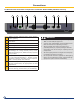
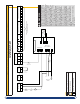
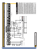
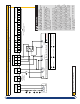
S2NA (ME50) or S3NA (MD5) Temperature control panel (Field Wiring Diagram)
Internal wiring by DDR-De Dietrich Factory
1 2 3
4
5 6
7
9 10
11
8 13 14
12
16
15
18 1917
21
20 23
24
22 2625 28 29
27
3130
33
3432 3635 38
37
120/60/1
Main Power Supply
Optional
thermostat TT
connection
CS – Safety
Contact 120v
1
st
Stage
2
nd
stage
N Gnd
Heating
Pump
Relay
L
N X
X
Limit Circuit
X X
2
nd
stage
controller
Burner Connections
L
N
Burner main
power
DHW
Pump
120/24v
Transformer
Burner Connections
Main Power 120/60/1
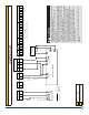
External Controller External control sensor wiring
Optional field wiring
terminals for
external control
Terminals for Optional Digital Control
or external control
1
2
3
4
5 6
1
2
3
4
5
6
Field Wiring Callout Notes
Fuse disconnect 15A Max.
Service Switch
Low water cut-off control
External Limit (Optional)E xternal Start/Run Interlock (Optional)
X
= Terminal designation
consult burner wiring
diagram or manufacturer
Vent Safety Switch, unless burner is
equipped with High gas or Pressure switch
Burner motor power supply may be from seperate disconnect if power
exceed 120V ±10% - 10A @ 60Hz. Or is multi-phase
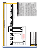
WARNING
FAILURE TO FOLLOWING THIS WIRING
DIAGRAM MAYRESULT IN PROPERTY DAMAGE
OR PERSONAL INJURY INCLUDING DEATH.
Wiring must be in strict compliance with CSA
C22.2 and NEC/NFPA 70. All wiringshown
supplied and wired by others. Optional 2
nd
stage relay supplied by others or ordered
loose, relay can be mounted in panel or
directly on burner.
This equipment must be earth bonded or
grounded.All wiring (eld or replacement)
must be min 18AWG type CSA TEW/ UL 1015
rated 105°C or an approved equivalent. All
wiring and panels must be shielded from spray
or ingestion of water. Any portion of the control
which has been subject to spray or ingestion
of water, the entire control must be replaced.
It is the responsibility of the installer/owner to
verify the controls are functioning correctly and
are adjusted correctly.Suitable wire protection
and strain relief’s are required (upstream &
downstream) of the control panel. Line voltage
wiring and low voltage sensor wiring must use
separate wire conduits.
LABEL ALL WIRES PRIOR TO DISCONNECTING
THEM FOR SERVICE.
Field wiring shown (By Others)