
Operation Manual


61
GT 530ADDR_G30A/AE _IO_V4.0 09/2013
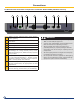
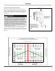
Typical flush to recessed combustion
head position application
D
A
C
B
E°
F
G
H
H
D
C
B
G
Typical protruding combustion
head position application
A
Burner installation on boiler burner door
A
Overall diameter including gap between head
and refratory material, including tappering
B
Burner combustion head diameter (consult
burner documentation)
C
0.18 –0.3 Inch gap between combustion head
and refractory material
D Burner door thicknessgt 530a = 5.51” /140Mm
E
Degree of tapper required on refactory material
to allow proper ame pattern
F
Maximum position combustion head shall be
recessed in the refractory material ¼ -½ inch
max
G Burner combustion head
H Burner ange with appropiate gasket
ATTENTION INSTALLER:
The burner as provided may have the burner mounting
bolts attached, but the door refractory insulation has
not be modied. This must be done by the installer.
Please consult the burner mounting instructions, for
any special modications required,
The refactory can be easily cut with a sharp knife or
any ne tooth cutting blade.
Note:
1. Burners that have a ush combustion head position
will require that the insulation be tappered to allow
sufcent space for proper ame pattern. Do not recess
combustion head inside refractory material more than
½ inch [12mm]
2. Burners that the combustion head is protruding past
the refactory material, no tappering is required. Consult
burner manufacturer to ensure combustion head
protruding into combustion chamber is acceptable.
WARNING
when cutting refractory special care must be taken or
damage to refractory will occur. Damage caused by
mistakes will not be covered under warranty.
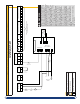
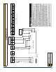
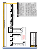
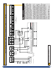
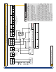
Connections
1
Refractory material holding screws
2
Insulation (soft) x2
1
Refractory material
GT530A Series Burner Door