
Operation Manual


54
GT 530A DDR_G30A/AE _IO_V4.0 09/2013
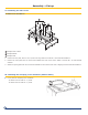
49. Electrical Connections
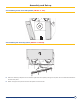
50. Installing the lower front panel (MR245 or MR246)
All connections are made with the terminal boxes
designed for that purpose on the back of the boiler's
control panel
Bring the burner cable behind the casing support
and down to the burner between the side panel and
insulating material.
v
Refer to the control panel instructions to
make the electrical connections.
see the “Electrical connections” section of
the instructions supplied with the control
panel
Place the insulation in the lower central front panel (black cloth facing outward).
Fit the lower central front panel (package FA5 or FA6) onto the lower front crosspiece and attach it to the boiler door.
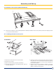
Assembly + Set up