
Operation Manual


32
GT 530A DDR_G30A/AE _IO_V4.0 09/2013
Assembly + Set up
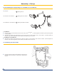
B
A
Front
GT 530A 15-19
GT 530A 20-32
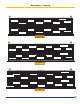
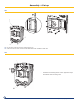
Assemble the well for the thermostats and thermometer in :
The third special intermediate section -5
15/16
”
/
151mm wide, 1/2’’ hole for GT 530A-15 to GT 530A-19
or
the fourth special intermediate section - 5
15/16
”
/
151mm wide, 1/2’’ hole for GT 530A-20 to GT 530AE-32.
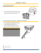
Plug the 2 free 1/2’’ holes for GT 530-15 to GT 530A-19 or the 3 free 1/2’’ holes for GT 530A-20 to GT 530AE-32 in the
special intermediate sections.
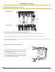
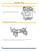
13. Assembling the pocket and the plugs
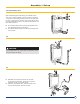
Fitting the upper and lower front anges
Fit the plain ange onto the upper connection of the
front section (using 4 M18 nuts), with the Ø 6
11/16
X
8
3/4
/
170x222 gasket in between (rst soak the gasket
in warm water prior Touse).
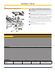
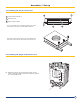
Fit the ange with the sludge removal hole onto the
lower connection of the front section (hole in the lower
part of the ange) using 4 M18 nuts, with the gasket in
between (soak in warm water rst).