
Operation Manual


46
De Dietrich Gas 310/610 ECO
11.0 CONTROL AND SAFETY EQUIPMENT
11.1 General
The boiler is supplied with a standard set of defaults pre-programmed for normal operation but can be tailored by
the engineer to suit most site conditions. These values are set and read, using the built-in instrument panel or
with a laptop/computer or PDA (with optional software and interface).
For tamper proofing and security reasons the control has three levels of access:
1. User level - owner access
2. Service level - access with service code by qualified personnel
3. Factory level - access by PC with factory code
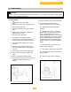
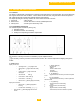
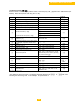
11.1.1 Instrument panel layout
The instrument panel consists of (see fig. 25):
1. Operating switch
2. PC/PDA connection for monitoring
3. Facility for incorporating a weather compensator
Fig. 25 Instrument panel
The functions of the keys and read-out windows (a-h) are explained below.
A summary of the key functions can be found in section 16.1 which is helpful when stepping through the
modes.
a. Code window:
Display at user level:
▪ operating mode = only digit or letter
▪ setting mode = digit or letter with steady
dot
▪ read-out mode = digit or letter with
flashing dot
▪ shut-off mode letter
▪ forced mode = ‘HIGH’ letter
▪ forced mode = ‘L°W’ letter
▪ failure mode = flashing digit (current fault)
Display at service level:
▪ failure mode = flashing digit (failure
memory)
▪ counter mode = alternating + +
▪ shut-off mode = alternating digit and dot in first
section
b. window displaying:
- temperatures
- settings
- shut-off or failure codes
c. reset key:
- reset/unlock key
d. key (mode key):
- program function; use this key to select the required
mode
e. Key (step key):
- program function; use this key t° select a parameter
within the mode
f. key (stare key);
- program function; increase setting
g. [+] k
ey:
-program function; increase setting
h. [-] key:
- program function; decrease setting
- switch function; manual or automatic °operation