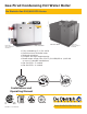
Gas-Fired Condensing Hot Water Boiler De Dietrich Gas 310/610 ECO Series Gas 310 ECO Boiler may not be exactly as illustrated. Gas 610 ECO Boiler may not be exactly as illustrated. • • • • • Fully modulating (5:1) 20-100% Cast Aluminum sectional boiler Reduced emissions Compact and light weight design Broad output range from 63 to 3,911 MBH/18 to 1,146 kW or more in cascade installations • Gas 310 ECO - 5 models • Gas 610 ECO - 4 models Installation and Operating Manual G310E 01 v1.0 04/2010 www.
De Dietrich Gas 310/610 ECO Warning: Before you operate this boiler, read this manual carefully and take extra precautions to all safety and warning symbols or important items. The operating manual is part of the documentation along with the boiler. The installer is required to explain your heating system and boiler operating instructions. Notice: Please read t his manual and retain f or future reference.
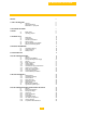
De Dietrich Gas 310/610 ECO TABLE OF CONTENTS PREFACE 5 1. SAFETY INSTRUCTIONS 1.1 Symbols General Instructions Modifications – Spare parts 6 6 6 6 2. DESCRIPTION OF BOILER 7 3. DESIGN Boiler version Operating principle 8 8 9 Dimensions Technical data Quotation specifications Delivery options Gas 610 Quotation Specification Delivery and ordering options 10 10 11 16 16 17 17 3.1 3.2 4. TECHNICAL DATA 4.1 4.2 4.3 4.4 4.5 4.6 5. EFFICIENCY INFORMATION 5.1 Combustion efficiency 5.
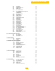
De Dietrich Gas 310/610 ECO 8.3 8.4 8.5 8.6 8.6.1 Connections Wiring diagram Sequence of operation Boiler control Gas 310 Introduction 30 31 34 34 34 8.6.2 Gas 310 Modulating controls general A. Single boiler B.
De Dietrich Gas 310/610 ECO 13.2.1 13.2.2 13.2.3 13.2.4 13.2.5 13.2.6 13.2.7 13.2.8 13.2.9 13.2.10 13.2.11 13.2.12 13.2.13 13.2.14 13.2.15 14. FAULT-FINDING 14.1 14.2 14.3 14.
De Dietrich Gas 310/610 ECO PREFACE Read t hese i nstructions c arefully, bef ore pu tting t he boi ler i nto op eration, f amiliarize your-self w ith i ts control f unctions, op eration and s trictly observe t he instructions g iven. F ailure t o do s o m ay invalidate warranty or prevent the boiler from operating. The Installation and commissioning of the boiler needs to be performed by a licensed and trained heating contractor.
De Dietrich Gas 310/610 ECO 1 SAFETY INSTRUCTIONS 1.1 Symbols The f ollowing symbols are us ed in t his d ocument to emphasize certain instructions. This is i n order t o increase your personal safety and to safeguard the technical reliability of the boiler. Instructions must be followed closely to avoid personal injury or serious damage to the unit or the environment. Important!! Instructions are of essential importance for the correct functioning of the unit.
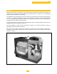
De Dietrich Gas 310/610 ECO The boiler must not be modified or fitted with non OEM spare parts without the express written approval of DDR Americas Inc. [De Dietrich Boilers]. 2 GENERAL DESCRIPTION OF BOILER The Gas 310/610 ECO boiler is a fully assembled, free standing, gas fired (natural gas only), fully modulating, high efficiency condensing boiler and is supplied, plastic wrapped, crated on a pallet.
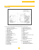
De Dietrich Gas 310/610 ECO 3 DESIGN 3.1 Boiler Version Fig. 02 Cross-section Gas 310 ECO (Left hand boiler illustrated). Gas 610 boiler consists of Gas 310-L and Gas 310-R. The service side of the boiler (with the heat exchanger inspection cover) is the front. 1. T/P gauge (supply manifold) 2. Relief valve 1 ½ In. & additional ½ In. port for external Hi limit 3. Flow-connection 4. Not available 5. Return-connection 6. Filling/drain cock 7. Condensate collector 8. Flue gas temperature sensor 9.
De Dietrich Gas 310/610 ECO e. Flue gas damper (optional for Gas 310 boiler, standard for Gas 610 boiler) 3.2 OPERATING PRINCIPLE Combustion air is drawn into the inlet connection from the plant room (room ventilated version) or from outside via the eccentric flue system (room sealed) by an air supply fan. On the inlet side of the fan is a specially designed chamber (venturi unit) which takes gas from the multi-block and mixes it in the correct proportions with the incoming air.
De Dietrich Gas 310/610 ECO 4 TECHINCAL DATA 4.1 Dimensions fig. 03 Elevation drawings Flow connection Return connection Gas connection Condensate drain Flue gas discharge Combustion air supply 3 inch ANSI 150# flange 2.
De Dietrich Gas 310/610 ECO 4.
De Dietrich Gas 310/610 ECO Gas610-6 Gas610-7 Gas610-8 Gas610-9 Model Gas610-6 Gas610-7 Gas610-8 Gas610-9 Model Gas610-6 Gas610-7 Gas610-8 Gas610-9 In. mm 40.5 1029 27 In. mm 22.2 564 A 685 14.4 In. mm 6.7 170 G 365 10.2 In. 57.6 mm 1463 72.95 1853 In. 35.5 43.7 39.6 35.6 H M I N In. mm 57.4 1457 E In. mm In. mm 258 57.1 1450 50.8 1290 mm 901 1110 1007 904 In. mm In. mm 26.8 680 55.2 1402 J O K P In. 51.7 mm 1312 In. 63 mm 1600 67 1702 78.
C De Dietrich Gas 310/610 ECO A A C D Gas 610 ECO Series Service & Combustible Clearances (MIN) A* B C D In. mm In. mm In. mm In. mm 12 300 12 300 31.5 800 24 600 Gas 610 ECO Series Base & leveling legs dimensions Model Gas610-6 Gas610-7 Gas610-8 Gas610-9 A In. 57.08 B mm In. 1450 24.8 C D mm In. mm 630 4.1 104 In. mm 1590 62.6 1980 13 F2 (Square) E 78 In. 44 mm 1118 59.4 1508 In. mm 2.
De Dietrich Gas 310/610 ECO Boiler Model Unit De Dietrich Gas 310 ECO 310-5 310-6 310-7 310-8 310-9 General On-Off, 2 Stage or Fully Modulating Firing Sequence Operation Minimum Fuel Input MBH [kW] 205 [60] 256 [75] 311 [91] 358 [105] 413 [121] Maximum Fuel Input MBH [kW] 1,017 [298] 1,269 [372] 1,529 [448] 1,785 [523] 2,041 [598] Minimum Heat Output MBH [kW] 191 [56] 242 [71] 287 [84] 334 [98] 386 [113] Maximum Heat Output MBH [kW] 962 [282] 1,205 [353] 1,457 [427] 1,703
De Dietrich Gas 310/610 ECO CSA Certified Avg. 97.4 – (potential up to ≅ 99.9%) 95.3 – (potential up to ≅ 99.9%) 3.5-14/8.
De Dietrich Gas 310/610 ECO 4.3 GAS 310 ECO QUOTATION SPECIFICATION: Fully assembled cast aluminum floor standing sectional hot water boiler. Premix burner with stainless steel cylinder with perforated holes for precise air-fuel mixture and velocity with a stainless tube with woven steel fiber for stable flame and heat insulation. Fully condensing boiler. ASME approved design, CRN for each Canadian Province. Precise air to fuel ratio through firing range with high turn down 5:1.
De Dietrich Gas 310/610 ECO 4.5 GAS 610 QUOTATION SPECIFICATION: Fully assembled cast aluminum floor standing sectional hot water boiler. Premix burner with stainless steel cylinder with perforated holes for precise air-fuel mixture and velocity with a stainless tube with woven steel fiber for stable flame and heat insulation. Fully condensing boiler. ASME approved design, CRN for each Canadian Province.
De Dietrich Gas 310/610 ECO 5 EFFICIENCY INFORMATION 5.1 Combustion efficiency ▪ Theoretically efficiency up to 99.9% can be achieved with return water temperature of 104°F [40°C], the combustion efficiency according to ANSI Z21.13b-/CSA 4.9b-2007 average = 95.3% 5.2 Thermal efficiency [heat to water] ▪ Average thermal efficiency 97.4% 5.3 Standby losses ▪ Less than 0.
De Dietrich Gas 310/610 ECO It is advisable (preferable) to install the Gas 310 ECO as follows: C C Place the crate c/w the boiler in the Single boiler “right hand version” Single boiler “left hand version” boiler room. Make sure there is enough room at one end of the crate for the boiler and ramp and clearance for the crate to be removed (at least 10ft [3M]). Place the 4 support pads under the adjustment bolts.
De Dietrich Gas 310/610 ECO It is advisable (preferable) to install the Gas 610 ECO as follows: Place the crate c/w the boiler in the boiler room. Make sure there is enough room at one end of the crate for the boiler and ramp and clearance for the crate to be removed (at least 10ft [3M]). Place the 4 support pads under the adjustment bolts. Use the adjusting bolts to jack up the boiler – lifting it clear of the wheels and with the top of the condensate collector level. Fit the siphon assembly.
De Dietrich Gas 310/610 ECO 7.3 Flue gas discharge and air supply Venting any flammable liquids, fluids, vapors or materials near the vicinity of the boiler. 7.3.1 General The Gas 310/610 ECO is suitable for both conventional room-supplied or direct vent (sealed combustion air) applications. All vent terminals should comply with the local and national codes. Any horizontal pipe-work in the flue gas discharge system should slope towards the boiler.
De Dietrich Gas 310/610 ECO 7.3.6 Conventional Chimney & CLV Systems Application Requirements: Warning: The boiler should never be operated in a negative building pressure. Caution should be exercised with exhaust fans, air handling & other devices, that could affect the buildings air pressure or combustion air supply. All venting must be arranged to avoid and prevent the accumulation of flue gas condensation.
De Dietrich Gas 310/610 ECO 7.3.6 Continued á L = Max L = Max CLV (different pressure zones) application with Direct vent (Sealed Combustion Air) supply à CLV system application (Different Pressure Zones) This venting system uses two separate vents that terminate a different points of the building (2 different pressure zones), a vent for combustion air and another for the flue gases. All combustion air is from the outdoor source.
De Dietrich Gas 310/610 ECO Warning & precautions: Venting lengths must not exceed the minimum and maximum equivalent lengths shown in table 07. Any horizontal runs of the venting must slope towards the boiler ½” per linear foot. This venting system uses a single vent to discharge all flue gases to the outside, combustion air provided within the boiler room, the air source must be sized in accordance to national codes CSA B149 & ANSI Z223.
De Dietrich Gas 310/610 ECO 7.3.9 Vent terminations installation precautions: [Consult national & local codes for other requirements] All exhaust terminations for conventional chimney must be finished with a finishing cone with tapered end, with a bird/rodent screen. All sidewall, direct vent, CLV systems must be finished with either a 90° elbow TEE termination, the combustion air inlet must be a 90° and must be provided with a debris/bird-rodent screen.
De Dietrich Gas 310/610 ECO 7.4 INSTALLATION DETAILS 7.4.1 Water pressure The boiler is suitable for a maximum working pressure of 100 psi [6.8 bar], the system pressure shall be at least 12 psi [0.8 bar] 7.4.2 Condensate discharge Discharge the condensate directly into a drain. Only use synthetic material for the connecting pipe-work because of the acidity of the condensate (pH 2-5) and allow a min. 1.2 inch per 3 ft. [30mm per meter fall], to ensure a good gravity siphon flow rate.
De Dietrich Gas 310/610 ECO 7.6 Typical water system layout The piping diagram illustrates the minimum boiler system controls needed, the by-pass system is not necessary, but can be used in multiple heating temperature circuits. Consult all national, local and building codes having jurisdiction for other requirements regarding the boiler system. It is strongly suggested a decoupling devise is used when the system flow is unknown. For multiple boilers, consult the factory.
De Dietrich Gas 310/610 ECO 8 INSTALLATION INSTRUCTIONS FOR ELECTRICAL INSTALLER 8.1 General The De Dietrich Gas 310/610 ECO is supplied as standard with electronic operating and flame ionization safety controls with a specially designed microprocessor at the heart of the system. The boiler is pre-wired as shown in the wiring diagram in fig. 18. All external connections can be made on the terminal strips (one low voltage 24V AC and one main power voltage 120V AC).
De Dietrich Gas 310/610 ECO 8.2.4 Fuse ratings Fuses on the circuit board on the control unit: F1 – 2 AF mains voltage fuse (automatic fuse) F2 – 2 AT for gas valve multiblock F3 – 2 AT for 24 V circuit F10 – 2 AT for shunt pump F11 – 1 AT for flue gas damper F12 – 1 AT for butterfly valve F13 – 2 AT for heating pump F14 – 1 AT for external gas valve Fig. 15 – Fuse plan The boiler fuse Fa is located behind / next to the 120V terminal strip.
De Dietrich Gas 310/610 ECO 8.3 Connections The terminal strips and boiler connectors can be seen once the control box cover is removed. The left-hand terminal strip (X29) is used for 24-volt connections. The right-hand terminal strip (X27) is used for 120-volt connections. All external connections are made on these terminal strips (see fig. 17). The various connections options are detailed in the following sections. Fig.
De Dietrich Gas 310/610 ECO 8.4 Wiring Diagram Fb 12AT fig.
De Dietrich Gas 310/610 ECO 8.
De Dietrich Gas 310/610 ECO Field wiring examples (Additional wiring examples are supplied separately) Example 1, local modulation LEGEND: Typical Gas310/610 boiler field wiring 1 Main fuse disconnect • • On/Off control or jumper – modulates according to internal set-point (Connect X29.9 & X29.10) LWCO & External Hi-Limit fault attenuation on control, connect devices in series on X29.1 & X29.
De Dietrich Gas 310/610 ECO 8.5 Switch sequence diagram 8.6 Boiler control 8.6.1 Gas 310 Introduction, Gas 610 each module Fig. 19 Switch sequence diagram [04.31H.79.
De Dietrich Gas 310/610 ECO 8.6.2 Gas 310 Modulating controls general (2 wire control) To make full use of the boiler’s modulating feature, a 0-10v [dc] input control will be needed. Some controls can provide weather compensation to achieve maximum efficiency and minimum boiler cycling whilst maintaining design condition within the building. A. Modulating boiler control [single boiler] An optional optimizing weather-compensated boiler control can be used for single boilers.
De Dietrich Gas 310/610 ECO Gas 310 Temperature based 68 – 194°F [20-90°C] Set the value of the boiler control operation parameter to . To set the ratio between voltage and the desired flow temperature (see par. 13.2.5 and fig. 21) 0 to 0.9 Volt 1 Volt 8 Volts = boiler off = Flow temperature set point 50°F [10°C] = Flow temperature set point 176°F [80°C] Output based – fixed parameters (20 to 100%) Set the value of the boiler control setting parameter to (see fig. 22) 0 to 1.
De Dietrich Gas 310/610 ECO Gas 610 Temperature based 68 – 194 F [20-90 C] set the value of the boiler control operation o o parameter to . To set the ratio between voltage and the desired flow temperature (see par. 13.2.5 and fig. 21) 0 to 0.9 Volt = boiler off o o 1 Volt = Flow temperature set point 50 F [10 C] o o 8 Volts = Flow temperature set point 176 F [80 C] Output based – fixed parameters (20 to 100%), set the value of the boiler control setting parameter to (see fig. 22) 8.6.
De Dietrich Gas 310/610 ECO 8.7.4 Other outputs 8.7.5 Analog output Depending on the option settings in the service level (see section 13.2.13), the analog output signal is able to transmit the following values: This output relates to terminals X29-13(+) and X29-14(-) Output Signal [0-10Vdc] 0 Volts 0.5 Volts 1.0 Volts 2.0 - 10 Volts Description Boiler off - standby Alarm Shut-off Output between 20 & 100% or Flow temperature between 68 – 212°F [20 - 100°C] table 06 - Analog °output signal 8.7.
De Dietrich Gas 310/610 ECO 8.8 Optional Inputs 8.8.1 System pressure sensor (optional) The system pressure sensor shutdown the boiler (with shutoff code ) when the minimum water pressure is reached (adjustable 11-100 psig [0.8 – 6 bar] factory setting = 14.5 psig [bar], see section 12.2.12) the hydraulic pressure sensor must be connected on the 5-pin female plug X22 on the 24-volt terminal strip.
De Dietrich Gas 310/610 ECO 8.8.5 Return butterfly valve 3-way valve (supplied by others) A butterfly valve should be installed in return for each boiler module is hydraulically disconnected from the system. The return butterfly valve is fully open the valve end switch contact is closed, allowing the boiler to run. The return butterfly valve must be connected to terminals X21-11 (neutral), X27-12 (power close) and X27-13 (power open) on the 120-volt terminal strip.
De Dietrich Gas 310/610 ECO 9.0 INSTALLATION INSTRUCTIONS FOR GAS INSTALLER 9.1 Gas connection The Gas 310/610 is suitable for use with natural gas only. The gas connection is at the top of the boiler (see fig. 02). The boiler is fitted with a gas filter as standard to prevent dirt from contaminating the gas valve or burner assembly. An isolating main gas cocks must be installed in the vicinity of the boiler.
De Dietrich Gas 310/610 ECO 10.0 COMMISSIONING Warning: If you do not follow the commissioning instructions exactly, a fire or explosion may result causing property damage, personal injury or loss of life. 10.1 Initial lighting 15. Adjust the boiler controls to heat demand. 1. Isolate main power supply 2. Remove the casing on the inspection side. 3. Open the main gas valve. 4. Check the electrical connections including earth. 5. Fill the boiler and the system with water (approximate > 11 psi). 6.
De Dietrich Gas 310/610 ECO 17 Continued: a. Check and correct, if necessary, the boiler for correct gas/air ratio set-up. Checking takes place on full and part load, adjustment takes place only on the gas valve multiblock. For checking and adjusting are required: an electronic CO2-gauge (on the basis of O2) and a gas pressure gauge. Note that the opening (see fig. 24) around the measuring probe is sealed properly during measurement.
De Dietrich Gas 310/610 ECO 18. Check gas leakage control and minimum gas pressure switch (if installed); Parameter must be set to a value greater than or equal to 8, depending on the connected options (see section 13.2.13). Then set the gas leakage control pressure switch to a switch pressure equal to 50% of the inlet pressure. Check that the measured inlet pressure is not the (higher) closing pressure. 19. Return the boiler to ‘user level’ by pressing the reset key. o ° 20.
De Dietrich Gas 310/610 ECO 10.2 Shutdown 1. Switch off the on/off switch of the boiler. With this, a possible boiler control will be without power. 2. Close the main shutoff valve.
De Dietrich Gas 310/610 ECO 11.0 CONTROL AND SAFETY EQUIPMENT 11.1 General The boiler is supplied with a standard set of defaults pre-programmed for normal operation but can be tailored by the engineer to suit most site conditions. These values are set and read, using the built-in instrument panel or with a laptop/computer or PDA (with optional software and interface). For tamper proofing and security reasons the control has three levels of access: 1. User level - owner access 2.
De Dietrich Gas 310/610 ECO 11.1.2 LED indicators The instrument panel has 4 indicating LED’s with the following functions: ▪ The LED above the [-] key (in the symbol); when illuminated green confirms the boiler is in manual override (see section 11.2) ▪ The LED above the [] key indicates that “24 hour pump operation” has activated the heating pump (and the shunt pump if required).
De Dietrich Gas 310/610 ECO 11.3 Display of value The display has only two digits available therefore values over this are displayed as followed: ▪ Values from 00 to 99 will be indicated without any decimals points. ▪ Values from 100 to 199 will be indicated by a dot between both digits e.g. =100, =110, =199 ▪ Values from 200 to 299 will be indicated by a dot behind every digit e.g.
De Dietrich Gas 310/610 ECO 12.2 Read-out mode () Read-out mode is used to display various values. Press the key until appears in the code window (dot flashes). Select the required code using the key.
De Dietrich Gas 310/610 ECO 12.3 Control strategy During normal operation, the boiler control can operate according to a specific strategy. Most control strategies are meant to keep the boiler burning for as long as possible, regardless of changes in flow and flow problems, etc. The control strategies can be viewed in read-out mode with the code .
De Dietrich Gas 310/610 ECO 12.5 Counter mode ( , and ) (service level) 12.5.1 General The boiler control records various data on the combustion trend of the boiler. This data can be read out in counter mode. The following data can be read out: ▪ Hours run ▪ Total number of start attempts ▪ Number of shunt pump operating hours ▪ Number of shunt pump starts ▪ Number of internal resets (control unit) ▪ Number of hours energized (control unit) 12.5.
De Dietrich Gas 310/610 ECO 13.0 SETTING MODE 13.1 User level setting mode () Setting mode is used to change various settings to suit individual requirements. The required code is selected by pressing the key until appears in the code window. Select the required code with the key. Now press the [+] key to increase a setting or the [-] key to decrease a setting. Press the key to stare the new setting. The new value will flash twice in the window to confirm the setting.
De Dietrich Gas 310/610 ECO 13.1.2 Pump run on time () Pump run on time can be adjusted (Please refer to Code installation contractor) -Press the -key until the digit (with dot) appears in the code-display. -Press the -key until the digit (with dot) appears in the code-display. -Set the required value, using the [+] and [-]-keys. ▪ Press the -key to stare the new value (value will flash twice). ▪ Press the reset-key to return to operating mode.
De Dietrich Gas 310/610 ECO Code Description Minimum fan speed (hundreds) see section 13.2.1 Setting Range Factory setting - x 100 rpm 310/610-5 = 15 = 1500 rpm 310/610-6 = 16 = 1600 rpm 310/610-7 = 11 = 1100 rpm 310/610-8 = 11 = 1100 rpm 310/610-9 = 12 = 1200 rpm Minimum fan speed (units) see section 13.2.1 - x 1 rpm Maximum fan speed (hundreds) see section 13.2.
De Dietrich Gas 310/610 ECO 13.2.1 Minimum fan speed ( and ) Parameter , adjustable between 06 and 60 (x100 rpm) parameter , adjustable between 0 and 100 (x 1 rpm). This setting is only active if setting has been selected in the boiler control: high/low control (see section 13.1.3). The value relates to the percentage output when the boiler is running at ‘low’. The percentage ‘high’ position depends on the set maximum central heating speed. 13.2.
De Dietrich Gas 310/610 ECO 13.2.8 T from control stops point to start point Parameter , adjustable from 9 to 36°F [5 to 20°C] This value sets the flow temperature at which the boiler will cut back in after a control stop. The boiler will always goes to a control stop when the flow temperature equals the flow set-point temperature > +9°F [> +5°C] The T defines when the burner is switched on again.
De Dietrich Gas 310/610 ECO Example (Factory setting is always = 0) Options Boiler water pressure sensor off Water pressure sensor on = 1 Analog output % = 0 Gas leakage control VPS on = 8 Imperial units of / PSI = 16 Boiler water pressure sensor on 1 Analog output Heat output % 0 ▪ ▪ ▪ ▪ Value 0 Analog output Temperature of [°C] 4 Gas leakage control VPS off 0 Gas leakage control VPS on 8 Metric units °C & bar 0 Imperial units °F & psi 16 Parameter : Sum … The sum of these settings
De Dietrich Gas 310/610 ECO 14 FAULT-FINDING Code Description Failure code (see table 19) (section 12.
De Dietrich Gas 310/610 ECO 14.4 Failure (lock-out) codes (requires user intervention, manual reset of control) When a failure code is displayed, both the code window and the window will flash alternately. Except for failure (does not flash).
De Dietrich Gas 310/610 ECO - Fan defective - Fan cable is corroded, resulting in absence of voltage or control signal. - Check the fan cable connectors on both the fan and the automatic burner unit side.
De Dietrich Gas 310/610 ECO 15 INSPECTION AND MAINTENANCE INSTRUCTIONS 15.1 General The De Dietrich Gas 310/610 ECO has been designed to need minimum maintenance, but to ensure optimum efficiency, we advise that once a year the boiler should be checked and if necessary cleaned and reset. All service and maintenance must be carried out by a qualified heating contractor with the relevant training and certifications. 15.
De Dietrich Gas 310/610 ECO 15.4 Maintenance If during the annual inspection combustion results indicate that the boiler is no longer operating at the optimum level additional maintenance should be carried out as follows: The Gas310/610 ECO boiler or any of its components does not contain any crystalline silica. Warning – Electrical Shock Hazard: Please label all wires prior to disconnecting when servicing this boiler. Wiring errors can cause improper operation and dangerous operation.
De Dietrich Gas 310/610 ECO 15.4.4 Cleaning the fan Use compressed air or a synthetic brush to clean the fan, be careful not to disturb the balance clips on the vanes. Fig. 31 fan being cleaned with soft brush 15.4.5 Cleaning the heat exchanger Release the retaining nuts from heat exchanger cover plate, remove plate, being careful not to damage the gasket, store safely.
De Dietrich Gas 310/610 ECO 15.4.7 Cleaning the condensate collector Clean the condensate collector by removing the inspection cover (next to the flue gas discharge) and then rinsing the collector with water Fig. 34 – Condensate collector inspection 15.4.8 Cleaning the siphon Remove the complete siphon (located underneath condensate collector beneath the flue connection). Remove siphon, clean and refill with clean water and re-fit. Fig. 35 – Condensate siphon assembly 15.4.
De Dietrich Gas 310/610 ECO 15.4.10 Gas filter check Measure the pressure differential P at measuring points, Pi and Pu (see fig. 37) on the gas filter. • If the P value is above 4.0” w.c. [10 mbar]: gas filter must be replaced. • If the P value is between 2.4 - 4.0” w.c. [6-10 mbar]: measure outgoing pressure on Pu. If this value is below 7” w.c. [18 mbar]: gas filter must be replaced. • If the P value is below 2.4” w.c. [6 mbar] Fig. 37 – Gas filter measuring points 15.4.
De Dietrich Gas 310/610 ECO 15.
De Dietrich Gas 310/610 ECO Fig.
De Dietrich Gas 310/610 ECO S54520 S54521 S54522 S54523 S54524 53544 55558 S54538 S54539 S54540 S54541 S54542 593 S54533 S54534 S54535 S54536 S54537 22222 S54548 S49297 54598 S54529 54562 S100435 S100436 S100437 S100438 S100439 S58818 S58611 54587 S100114 S100440 S48950 113324 113323 113325 113327 113326 S59727 S58823 Access plate heat exchanger 5 sections Access plate heat exchanger 6 sections Access plate heat exchanger 7 sections Access plate heat exchanger 8 sections Access plate heat exchanger 9 sect
De Dietrich Gas 310/610 ECO 16 ADDENDICES 69
De Dietrich Gas 310/610 ECO 16.1 Control menu Fig.
De Dietrich Gas 310/610 ECO 16.
De Dietrich Gas 310/610 ECO 16.
De Dietrich Gas 310/610 ECO 17 BOILER COMMISIONING REPORT & MAINTENANCESCHEDULE 17.
De Dietrich Gas 310/610 ECO 17.2 Boiler Control Settings Site Applied Boiler Control Settings: [Setting Mode] Advanced Setting Mode – Service Level 17.
DDR Americas Inc. 1054 North DuPage Avenue Lombard, Illinois 60148 USA Tel: 630-953-2374 / Fax: 630-953-2376 1090 Fountain Street North, Unit 10 Cambridge, Ontario N3E 1A3 Canada Tel: 519-650-0420 / Fax: 519-650-1709 Toll Free: 800-943-6275 www.dedietrichboilers.com info@dedietrichboilers.com G310E 01 v1.