
Operation Manual


54
De Dietrich Gas 310/610 ECO
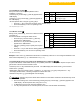
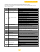
Code Description Setting Range Factory setting
Minimum fan speed (hundreds)
see section 13.2.1
- x 100 rpm
310/610-5 = 15 = 1500 rpm
310/610-6 = 16 = 1600 rpm
310/610-7 = 11 = 1100 rpm
310/610-8 = 11 = 1100 rpm
310/610-9 = 12 = 1200 rpm
Minimum fan speed (units) see section 13.2.1
- x 1 rpm
Maximum fan speed (hundreds)
see section 13.2.2
- x 100 rpm
310/610-5 = 5500 rpm
310/610-6 = 5600 rpm
310/610-7 = 3650 rpm
310/610-8 = 4200 rpm
310/610-9 = 4500 rpm
Maximum fan speed (units) see section 13.2.2
- x 1 rpm
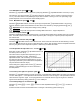
Forced part load running time, see section 13.2.3
- x 10 sec.
Cycling prevention delay-time, see section 13.2.4
- x 10 sec. = 20 seconds
Required flow temperature at 0 volts (analog signal), see
section 13.2.5
- = -58 to 122°
F or
- = -50°C to 50°C
Required flow temperature at 10 volts (analog signal), see
section 13.2.6
- , , , = 122 to 480°F or
-
= 50°C to 249°C
= 212°F or = 100°C
Switch point High/Low operation signal, see section 13.2.6
- x 100 rpm
310/610-5 = 3500 rpm
a) Signal "Low fire" if value less than
310/610-6 = 3900 rpm
310/610-7 = 2500 rpm
b) Signal "High fire" if value is greater than
310/610-8 = 2700 rpm
310/610-9 = 3500 rpm
Shunt pump post purge time, see section 13.2.7
= 1 seconds t° = minutes.
= continuous
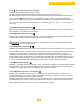
ΔT from control stop point start point, see section 13.2.10
- = 9 – 54°F
-
= 5 - 30°C
= 50 of or = 10°C
Maximum flue gas temperature, see section 13.2.9
- = 176 to 248°F
or
-
= 80 to 120°C
= 248 of or = 120°C
High limit temperature set point, see section 13.2.10
- = 194 to 212°F or
- = 90 to 100°C
= 212 of or
= 100°C
Modulation start point ΔT, see section 13.2.11
- = 9 to 54°F or
- = 5 to 30°C
= 45 of or = 25°C
Minimum water pressure, see section 13.2.12
- = x 0.1 bar units or x 14.5 psi units = 0.8 bar or 11.6 psi
Adjustments options/accessories, see section 13.2.13
-
"Low" fan speed with H/L control parameter =21, see
section 13.2.14
- = x 100
310/610-5 = 1500 rpm
310/610-6 = 1600 rpm
310/610-7 = 1100 rpm
310/610-8 = 1100 rpm
310/610-9 = 1200 rpm
Boiler type; Appears only after replacing the control unit
-
depends on output variant
Table 16 Service level setting mod