
Operation Manual

48
De Dietrich Gas 310/610 ECO
11.3 Display of value
The display has only two digits available therefore values over this are displayed as followed:
▪ Values from 00 to 99 will be indicated without any decimals points.
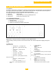
▪ Values from 100 to 199 will be indicated by a dot between both digits e.g.
=100, =110, =199
▪ Values from 200 to 299 will be indicated by a dot behind every digit e.g. = for 200, =210, =299
▪ Value over 300 will be indicated by showing the thousands, hundreds, tens and units in separate
alternating pairs. (see section 12.2 and 12.5)
▪ Negative values (for instance when using an external sensor or when sensors are not connected) will be
indicated by a dot behind the last digit, e.g. indicates -10.
12.0 OPERATING MODE
12.1 Operating mode ()
During normal operation the code-display show the status (position in cycle) of the boiler, with the -display
indicating the actual flow temperature.
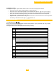
The digits or letters in the code-display have the following meaning:
Code
Description
Standby, there is no heat demand
Pre-ventilation (pre-purge time 30 seconds, post purge time 3 seconds)
Trial for ignition
Burner firing and flame detected
N/a
Waiting mode, startup check, air sensor LDs sufficient pressure
Control stop (burner off + post purge)
a) Flow temperature T1 > set point 9°F [+5°C]
b) Flow temperature T1 > desired set point modulating control 9°F [+5°C]
c) flow temperature T1 > parameter
d) Difference flow T1 and return T2 > 10°C (factory setting) Starting condition is ≤ 10°C
End of heating demand, pump post purge. During cycling prevention delay-time the boiler will
remain in state and will not react to heat demand.
N/a
Shut-off mode (see section 12.4)
Forced full load (HIGH)
Forced part load (LOW)
Gas leakage control
Burner cooling
Table 08