
Operation Manual

43
De Dietrich Gas 310/610 ECO
* For reference only. Measured combustion values more important.
17 Continued:
a. Check and correct, if necessary, the boiler for correct gas/air ratio set-up. Checking takes place on full and part
load, adjustment takes place only on the gas valve multiblock. For checking and adjusting are required: an
electronic CO
2
-gauge (on the basis of O
2
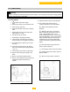
) and a gas pressure gauge. Note that the opening (see fig. 24) around
the measuring probe is sealed properly during measurement. Note also that measuring the O
2
levels in the flue
gas is necessary, because direct measurement of CO
2
can lead to inaccuracies due to varying CO
2
levels in the
natural gas. Connect the gas pressure meter between measuring point PG on the underside of the gas valve
multiblock and measuring point PL on the venturi (see fig. 23), ensuring the connections are gas tight.
a. Run the boiler at full load (forced mode ‘high’) by pressing the and [+]-key simultaneously for 2
seconds. The letter will now appear on the display.
b. When full load is reached, measure P gas at measuring point P on the underside of the gas valve
multiblock and at the measuring point PL on the Venturi and compare to the value in table 7 adjust if
necessary using the adjustment screw on the gas valve multiblock.
c. Check CO
2
- percentage (O
2
-percentage) against table 11. If the values exceed the given tolerances,
adjust according to fig. 23. Check the flame through the inspection glass, the flame must not blow off.
d. Run the boiler at part load (forced mode ‘low’) by pressing the and [-] keys simultaneously for 2
seconds. The letter will now appear on the display.
e. When part load is reached, measure P gas at measuring point P on the underside of the gas valve
multiblock and at measuring point PL on the Venturi and compare to the value in table 7 adjust if
necessary using the adjustment screw on the gas valve multiblock.
f. Check CO
2
-percentage (O
2
-percentage) against table 11. If the values exceed the given
tolerances, adjust according to fig. 23.
g. Remove measuring equipment and seal test points.
Check the flame through the inspection glass, the flame must not blow off. Repeat the check starting from
point 17b until the readings match the values in the tables. Contact our Service Department if deviations
cannot be corrected.
IMPROTANT SAFETY WARNING:
The installation of the boiler is not completed until all controls and safety device have been tested and
verified for correct function and operation. It is the sole responsibility of the installer to ensure that safety
control system and gas ignition system and any there safety control must be tested.
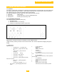
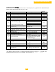
Gas Pressure Readings*
Boiler
Models
Full Load (100%)
Part Load (20%)
Δp [in w.c.] Δp [mbar] Δp [in w.c.] Δp [mbar]
310-5 5.20 ± 0.6 13.0 ± 1.5 0.28 ± 0.08 0.70 ± 0.20
310-6 4 ± 0.6 10 ± 1.5 0.18 ± 0.08 0.45 ± 0.20
310-7 3.80 ± 0.6 9.5 ± 1.5 0.20 ± 0.08 0.50 ± 0.20
310-8 5 ± 0.6 12.5 ± 1.5 0.30 ± 0.08 0.75 ± 0.20
310-9 6.20 ± 0.6 15.5 ± 1.5 0.32 ± 0.08 0.80 ± 0.20
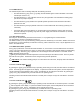
Combustion Readings
Emission Unit
Full Load
(100%)
Part Load
(20%)
CO
2
Range
%
9.0 ± 0.5
CO
2
Set Point
%
9.0 ± 0.15
O
2
Range
%
4.8 ± 0.5
O
2
Set Point
%
4.8 ± 0.25
CO Limit
ppm
< 100