
Operation Manual

23
De Dietrich Gas 310/610 ECO
7.3.6 Continued
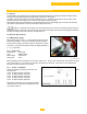
CLV system application (Different Pressure Zones)
This venting system uses two separate vents that terminate a
different points of the building (2 different pressure zones), a
vent for combustion air and another for the flue gases. All
combustion air is from the outdoor source. The vent terminal
shall discharge flue gases away from the building structure so
that the flue gases do not cause damage to the building. The
vent terminal locations follow local and national codes
requirements. [See section 7.3.9]
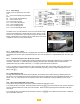
7.3.7 Sidewall vented application with or without direct vent (sealed combustion air):
Caution – Warning:
Flue gas condensation is very aggressive and corrosive
which could lead to failure of the venting system or
drains, consult local and national codes regarding flue
gas condensation disposal. The P-trap assembly must
be properly filled with water to avoid escape of the flue
gas emissions. The flue gas condensation may require
neutralization prior to entering the drain.
Warning:
An improperly sealed venting system could result in
carbon monoxide poisoning; ensure adequate support
and fastening of the system. Ensure venting can safely
exhaust all flue gases to the outside in a safe and
effective manner. Do not puncture or drill holes in any
portion of the venting, the boiler is equipped with a
pressure and emission test port. All venting must be
arranged to avoid and prevent the accumulation of flue
gas condensation.
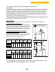
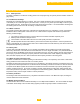
CLV vent systems venting length chart
Gas 310/610
Model
Vent ø
Vent Length
[Min]
Vent
Length
[Max]
90° Elbow =
Length
45° Elbow =
Length
inch
mm
Ft.
m
Ft.
m
Ft.
m
Ft.
mm
310-5
10 250 5 1.5 180 54 12 3.5 6.5 2
310/610-6
310/610-7
310/610-8
310/610-9
Table 04[c] - venting length chart.
Table also applies to Gas 610 models.
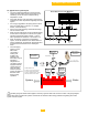
L = Max
Gas310 Eco Boiler
[Left hand version shown]
CLV (different pressure zones) application with
Direct vent (Sealed Combustion Air) supply
L = Max
Fig. 8
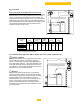
Gas310 Eco Boiler
[Left hand version shown]
Sidewall vented application with or without
Direct vent (Sealed Combustion Air) supply
L = Max
Fig. 9