
Operation Manual

22
De Dietrich Gas 310/610 ECO
7.3.6 Conventional Chimney & CLV Systems Application Requirements:
Warning:
The boiler should never be operated in a negative building pressure. Caution should be exercised with
exhaust fans, air handling & other devices, that could affect the buildings air pressure or combustion air
supply. All venting must be arranged to avoid and prevent the accumulation of flue gas condensation.
An improperly sealed venting system could result in carbon monoxide poisoning; ensure adequate
support and fastening of the system. Ensure venting can safely exhaust all flue gases to the outside in a
safe and effective manner. Do not puncture or drill holes in any portion of the venting, the boiler is
equipped with a pressure and emission test port.
Venting lengths values must be between equivalent lengths show in table 04a-b. Any horizontal runs of
the venting must slope towards the boiler ½” per linear foot. The length in the tables apply to each vent
length separately (air intake and flue gas exhaust)
Exterior Venting:
Any portion of the venting exposed the outside climate shall be suitable for exterior applications.
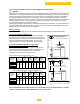
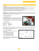
Conventional Chimney applications:
This venting system uses a single vent to discharge all flue
gases to the outside vertically, combustion air provided with
the boiler room, the air source must be sized in accordance to
national codes CSA B149 & ANSI Z223.1 or local codes
having jurisdiction, more than one source may be required.
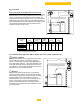
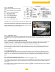
Conventional Chimney with direct vent (sealed
combustion air) applications:
This venting system uses either a co-axle or single vent for
both the air intake and the flue gas exhaust; the boiler room
does not require a combustion air source, as all air for
combustion is taken from the outside source.
Note: All lengths shown in table 04a-b are for a single boiler only. For multiple boilers (cascade)
common venting systems consult DDR Americas Inc. for assistance.
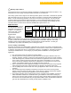
Chimney Application [room supplied combustion air]
Gas
310/610
Model
Vent ø
Vent
Length
[Min]
Vent
Length
[Max]
90°
Elbow =
Length
45°
Elbow =
Length
inch mm Ft. m Ft. m Ft. m Ft. m
310-5
10 250 5 1.5 250 76 12 3.5 6.5 2
310/610-6
310/610-7
310/610-8
310/610-9
Table 04[a] - venting length chart. Table also applies to Gas 610 models.
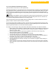
Chimney application with direct vent (sealed combustion air)
Gas
310/610
Model
Vent ø
Vent
Length
[Min]
Vent
Length
[Max]
90°
Elbow =
Length
45°
Elbow =
Length
inc
h
mm
Ft.
m
Ft.
m
Ft.
m
Ft.
m
m
310-5
10 250 5 1.5 200 60 12 3.5 6.5 2
310/610-6
310/610-7
310/610-8
310/610-9
Table 04[b] - venting length chart. Table also applies to Gas 610 models.
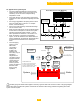
L = Max
Gas310 Eco Boiler
[Left hand version shown]
Convention Chimney application with
room supplied combustion air
Not shown air intake filter (recommended)
Fig. 7(a)
L = Max
Gas310 Eco Boiler
[Left hand version shown]
Convention chimney application with
Direct vent (Sealed Combustion Air) supply
Fig. 7(b)