Export HPI EVOLUTION EN Air / water heat pump AWHP-2 MIT-IN-2 iSystem User Guide 7616372-001-02
Contents 1 Introduction ................................................................................................4 1.1 Symbols used .......................................................4 1.1.1 1.1.2 1.2 Abbreviations ........................................................5 1.3 Liabilities ...............................................................5 1.3.1 1.3.2 1.3.3 1.4 3 2.1 Safety instructions ...............................................8 2.2 Recommendations ..................
Contents 5 6 4.4 Installation shutdown .........................................23 4.5 Turning on the antifreeze function ....................23 Troubleshooting .......................................................................................24 5.1 Anti-hunting ........................................................24 5.2 Messages .............................................................24 5.3 Faults (Code type Lxx or Dxx) ...........................26 Technical specifications ......
3 31/03/2014 - 7616372-001-02
1. Introduction AWHP-2 MIT-IN-2 iSystem 1 Introduction 1.1 Symbols used 1.1.1. Symbols used in the manual In these instructions, various danger levels are employed to draw the user’s attention to particular information. In so doing, we wish to safeguard the user’s safety, obviate hazards and guarantee correct operation of the appliance. DANGER Risk of a dangerous situation causing serious physical injury. WARNING Risk of a dangerous situation causing slight physical injury.
AWHP-2 MIT-IN-2 iSystem 1. Introduction 1.
1. Introduction AWHP-2 MIT-IN-2 iSystem 1.3.2. Installer’s liability The installer is responsible for the installation and inital start up of the appliance. The installer must respect the following instructions: 4 Read and follow the instructions given in the manuals provided with the appliance. 4 Carry out installation in compliance with the prevailing legislation and standards. 4 Perform the initial start up and carry out any checks necessary. 4 Explain the installation to the user.
1. Introduction AWHP-2 MIT-IN-2 iSystem 4 2004/108/EC Electromagnetic Compatibility Directive. Generic standards: EN1000-6-3 , EN 61000-6-1.
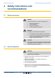
2. Safety instructions and recommendations AWHP-2 MIT-IN-2 iSystem 2 Safety instructions and recommendations 2.1 Safety instructions DANGER If smoke is released or in case of refrigerant leak: 1. 2. 3. 4. Switch the appliance off. Open the windows. Evacuate the premises. Contact a qualified professional. WARNING Depending on the settings of the appliance: 4 The temperature of the radiators may reach 80°C.
3. Description AWHP-2 MIT-IN-2 iSystem 3 Description 3.1 General description The AWHP-2 MIT-IN-2 iSystem heat pump is composed of two elements: 4 The outside unit handles energy production in hot or cold mode. 4 The inside module handles thermal exchange between the R410A fluid and the hydraulic circuit. The two units are connected by means of refrigeration and electrical connections. The system offers the following advantages: 4 The heating circuit is housed in the insulated volume within the home.
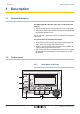
AWHP-2 MIT-IN-2 iSystem 3. Description A Temperature setting key (heating, DHW, swimming pool) B Operating mode selection key C DHW override key D Key to access the parameters reserved for the installer E Keys on which the function varies as and when selections are made ¼See: "Key functions", page 10 F Rotary setting button: 4 4 3.2.2.
AWHP-2 MIT-IN-2 iSystem L000199-A 3. Description The tank is not loaded - Presence of the solar control system n Operating modes 0 v c 4 6 8 10 12 14 16 18 20 22 1 1 2 w p b AUTO x c gm r j 0 2 4 6 8 10 M t STD 12 14 16 18 p Summer mode: Cooling is possible. Domestic hot water continues to be produced. b WINTER mode: Heating and domestic hot water working. w+p Forced cooling mode. w Cooling mode: Heating according to the time programme.
AWHP-2 MIT-IN-2 iSystem 3. Description n Domestic Hot Water override A bar is displayed when a DHW override is activated: 0 2 4 6 8 10 12 14 16 18 20 22 24 4 Flashing bar: Temporary override 4 Steady bar: Permanent override bar r j M C002707-A p b AUTO x c g m t STD n Electrical back-up G 0 v c 4 6 8 10 12 14 16 18 20 22 24 The symbol 1 or 2 lights up, depending on whether stage 1 or 2 on the electrical back-up is commanded.
3. Description AWHP-2 MIT-IN-2 iSystem n Other information 0 2 4 6 8 10 12 14 16 18 20 22 r The symbol is displayed when domestic hot water production is running. w Valve indicator: The symbol is displayed when a 3-way valve is connected. 24 bar r j M C002699-B p b AUTO x c g m t STD M 4 x: 3-way valve opens 4 c: 3-way valve closes The symbol is displayed when the pump is operating. Name of the circuit for which the parameters are displayed. 3.2.3.
AWHP-2 MIT-IN-2 iSystem 3. Description 7. To go back to the main display, press key j2 times. 0 2 4 6 8 10 12 14 16 18 20 22 24 2x LUNDI 11:45 v bar c 1 It is possible to use the ( and ’ keys instead of the rotary button.
AWHP-2 MIT-IN-2 iSystem 4. Operating the appliance 4 Operating the appliance 4.1 Putting the appliance into operation 1. Make a note of the output and type shown on the outside module’s nameplate. MW-M001832-2 2. Switch on the power by throwing the on/off switch on the inside module. C002366-B 0 v bar c 1 2 1 2 2 4 6 8 10 12 14 16 18 20 22 3. The first time the boiler is powered up, the LANGUAGE menu is displayed. Select the desired language by turning the rotary button. 4.
AWHP-2 MIT-IN-2 iSystem 4.2 4. Operating the appliance Reading out measured values The various values measured by the appliance are displayed in the #MEASURES menu. 1. To access user level: Press the > key. 0 2 4 6 8 10 12 14 16 18 20 22 24 2. Select the menu #MEASURES. SUNDAY 11:45 v bar c Turn the rotary button to scroll through the menus or modify a value. 4 Press the rotary button to access the selected menu or confirm a value modification.
4. Operating the appliance AWHP-2 MIT-IN-2 iSystem User level - Menu #MEASURES Parameter Description Unit DT INSTALLATION Installation temperature delta ELEC.ENERGY (1) ELEC.ENERG.Y1 (1) ELEC.ENERG.Y2 (1) THERM.ENERGY (1) K Total electrical energy consumed kWh Total electrical energy consumed in the previous year kWh Total electrical energy consumed two years ago kWh Total thermal energy yield kWh THERM.ENERG.Y1 Total thermal energy yield in the previous year kWh THERM.ENERG.
AWHP-2 MIT-IN-2 iSystem 4. Operating the appliance Menu C Parameter Adjustment range Description Factory setting 10 to 80 °C Set tank temperature, night programme 10 °C TEMP.TANK AUX (2) 10 to 80 °C Desired domestic hot water temperature in the auxiliary circuit 55 °C WATER T.NIGHTAUX (2) 10 to 80 °C Desired domestic hot water temperature in the auxiliary circuit for the night program 10 °C DHW A TEMP. (2) 10 to 80 °C Desired domestic hot water temperature in circuit A 55 °C WATER T.
AWHP-2 MIT-IN-2 iSystem 4. Operating the appliance Menu MODE Parameter Adjustment range Description Factory setting COLD Cooling mode is forced. MANUEL The generator operates according to the set point setting. All of the pumps operate. Option of setting the set point by simply turning the rotary button. FORCE AUTO (2) ON / OFF An operating mode override is activated on the remote control (option). To force all circuits to run on AUTOMATIQUE mode, select ON.
4. Operating the appliance AWHP-2 MIT-IN-2 iSystem User level - Menu #SETTING Parameter Adjustment range Description Factory setting Customer setting Adjusting the display contrast. CONTRAST DISP. BACK LIGHT COMFORT The screen is illuminated continuously in daytime periods. ECO The screen is illuminated for 2 minutes whenever pressed. 4.3.5. ECO Setting the time and date 1. To access user level: Press the > key. 0 2 4 6 8 10 12 14 16 18 20 22 24 2. Select the menu #TIME .DAY.
AWHP-2 MIT-IN-2 iSystem 4. Operating the appliance 4. Assign the desired timer programme (P1 to P4) to the circuit with the rotary button. User level - Menu #CHOICE TIME PROG. Parameter Adjustment range Description CURRENT PROG.A P1 / P2 / P3 / P4 Comfort programme activated (Circuit A) CURRENT PROG.B P1 / P2 / P3 / P4 Comfort programme activated (Circuit B) CURRENT PROG.C P1 / P2 / P3 / P4 Comfort programme activated (Circuit C) 4.3.7. Customising a timer programme 1.
AWHP-2 MIT-IN-2 iSystem 0 v bar c 1 2 1 2 2 4 6 8 10 12 14 16 PROG P2 C Mo Tu We Th Fr "Select the days to program" r p b AUTO x c g m ( ' r 4. Operating the appliance 18 20 Sa j 22 24 a Su L t STD 6. b: Day selection Press key b / v until the symbol b is displayed. Turn the rotary button to the right to select the day(s) desired. v: Cancelling the day selection Press key b / v until the symbol v is displayed.
AWHP-2 MIT-IN-2 iSystem 4. Operating the appliance User level - Menu #TIME PROGRAM Day Comfort periods / Filling enabled: P1 P2 _______________ P3 _______________ P4 _______________ _______________ TIME PROG.DHW Monday Tuesday Wednesday Thursday Friday Saturday Sunday TIME PROG.AUX Monday Tuesday Wednesday Thursday Friday Saturday Sunday EVU TIMER PROG. Monday Tuesday Wednesday Thursday Friday Saturday Sunday 4.
AWHP-2 MIT-IN-2 iSystem 5. Troubleshooting 5 Troubleshooting 5.1 Anti-hunting When the heat pump is in "anti-short cycle" operating mode, the symbol "?" flashes. This is a normal operating mode. When the restart temperature is reached, operation will be guaranteed. 1. Press the "?" key. The message Operation assured when the restart temperature will be reached is displayed. When the restart temperature is reached, operation will be guaranteed.
5. Troubleshooting AWHP-2 MIT-IN-2 iSystem Code Messages Description B09 The BL inlet on the PCU PCB The contact connected to the BL inlet is open. terminal block is open. Antifreeze 4 Contact the professional who takes care of protection. maintenance of the appliance. Parameter error. BL.SC.IN.OPEN Checking / solution Contact the professional who takes care of maintenance of the appliance. Bad connection. 4 Contact the professional who takes care of maintenance of the appliance.
AWHP-2 MIT-IN-2 iSystem 5. Troubleshooting Code Messages Description Checking / solution M04 A service is required. The date programmed for the service has been reached. REVISION 4 Service the heat pump. To clear the inspection, programme another date in the menu #REVISION or set the parameter REVISION TYPE to OFF. FL.DRY.B XX DAYS Floor drying is active. Floor drying is underway. Heating on the circuits not XX DAYS = Number of days’ floor concerned is shut down. FL.DRY.C XX DAYS FL.DRY.
5. Troubleshooting AWHP-2 MIT-IN-2 iSystem Code Faults Cause of the fault Description Checking / solution D03 D04 SCU Circuit B flow sensor fault Circuit C flow sensor fault Remarks: The circuit pump is running. The 3-way valve motor on the circuit is no longer powered and can be adjusted manually. Bad connection Sensor fault OUTL S.B FAIL. OUTL S.C FAIL. SCU D05 OUTSI.S.FAIL. D07 SYST.SENS.FAIL.
AWHP-2 MIT-IN-2 iSystem 5. Troubleshooting Code Faults Cause of the fault Description Checking / solution D19 SCU Header sensor fault Bad connection Sensor fault Contact the professional who takes care of maintenance of the appliance Interruption in communication between the SCU PCB and the solar control system SOL.COL.S.FAIL 4 D20 SOL COM.FAIL SCU D27 PCU COM.
6. Technical specifications AWHP-2 MIT-IN-2 iSystem 6 Technical specifications 6.1 Technical specifications 6.1.1. Electricity supply 230 V AC (+/- 10%) - 50 Hz 400 V AC (+ 6%, - 10%) - 50 Hz (depending on the model) 6.1.2.
AWHP-2 MIT-IN-2 iSystem 6. Technical specifications n Performances in hot mode with outside air temperature at +2°C and outlet water temperature at +35°C (in accordance with EN 14511–2) AWHP 4 MR 6 MR -2 8 MR-2 11 MR-2 11 TR-2 16 MR-2 16 TR-2 22 TR 27 TR Calorific output - A2/W35 kW 3.76 3.87 5.93 10.19 10.19 11.38 11.38 11.62 14.70 3.32 3.26 3.20 3.20 3.20 3.27 3.27 3.01 3.10 Absorbed electrical power - A2/W35 kWe 1.13 1.19 1.85 3.19 3.19 3.48 3.48 3.86 4.
6. Technical specifications AWHP-2 MIT-IN-2 iSystem 6.1.3.
7. Energy savings AWHP-2 MIT-IN-2 iSystem 7 Energy savings 7.1 Energy savings This chapter contains: 4 Energy-saving advice 4 Advice on setting the room thermostat correctly 7.1.1. Energy-saving advice 4 Do not block ventilation outlets. 4 Install reflective panels behind the radiators to prevent heat losses. 4 Do not cover the radiators. Do not hang curtains in front of the radiators. 4 Insulate the pipes in rooms that are not heated (cellars and lofts). 4 Close the radiators in rooms not in use.
7. Energy savings AWHP-2 MIT-IN-2 iSystem The setting of the control panel and/or of the remote control has a considerable influence on energy consumption. A few tips: 4 In the room in which the room thermostat is installed, it’s advised not to use thermostatic valve radiators. If a thermostatic valve is used the valve must be fully opened. 4 Completely closing and opening thermostatic valve radiators causes undesirable temperature fluctuations. Open and close thermostatic valves in small steps.
8. Warranty AWHP-2 MIT-IN-2 iSystem 8 Warranty 8.1 General You have just purchased one of our appliances and we thank you for the trust you have placed in our products. Please note that your appliance will provide good service for a longer period of time if it is regularly checked and maintained. Your installer and our customer support network are at your disposal at all times. 8.
DE DIETRICH THERMIQUE S.A.S +49 (0)25 72 / 9161-0 +49 (0)25 72 / 9161-102 info@remeha.de DE DIETRICH THERMIQUE Iberia S.L.U. www.dedietrich-calefaccion.es ES C/Salvador Espriu, 11 08908 L’HOSPITALET de LLOBREGAT +34 935 475 850 info@dedietrich-calefaccion.es 129164, Россия, г. Москва Зубарев переулок, д. 15/1 Бизнес-центр «Чайка Плаза», офис 309 +7 (495) 221-31-51 M001476-C DE DIETRICH SERVICE www.dedietrich-heiztechnik.com Freecall 0800 / 201608 IT BDR Thermea (Czech republic) s.r.o www.