Export MODULENS O EN ® Oil-fired condensing boilers AFC 18 - AFC 24 - AFC 30 User Guide 300026440-001-03
Contents 1 Introduction ................................................................................................4 1.1 Symbols used .......................................................4 1.1.1 1.1.2 1.2 Abbreviations ........................................................5 1.3 General ..................................................................5 1.3.1 1.3.2 1.3.3 1.4 2 3 Safety instructions and recommendations ..............................................7 2.
Contents 5 6 7 4.4 Installation shutdown .........................................23 4.5 Antifreeze protection ..........................................23 Checking and maintenance .....................................................................25 5.1 General instructions ...........................................25 5.2 Periodic checks ..................................................25 5.3 Filling the system ...............................................26 5.
3 09/01/2014 - 300026440-001-03
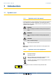
1. Introduction AFC 18 - AFC 24 - AFC 30 1 Introduction 1.1 Symbols used 1.1.1. Symbols used in the manual In these instructions, various danger levels are employed to draw the user’s attention to particular information. In so doing, we wish to safeguard the user’s safety, obviate hazards and guarantee correct operation of the appliance. DANGER Risk of a dangerous situation causing serious physical injury. WARNING Risk of a dangerous situation causing slight physical injury.
AFC 18 - AFC 24 - AFC 30 1. Introduction 1 Caution: danger, live parts. Disconnect the mains power prior to any operations. 2 M002628-A 1.
AFC 18 - AFC 24 - AFC 30 1. Introduction 1.3.2. Installer’s liability The installer is responsible for the installation and inital start up of the appliance. The installer must respect the following instructions: 4 Read and follow the instructions given in the manuals provided with the appliance. 4 Carry out installation in compliance with the prevailing legislation and standards. 4 Perform the initial start up and carry out any checks necessary. 4 Explain the installation to the user.
AFC 18 - AFC 24 - AFC 30 2. Safety instructions and recommendations 2 Safety instructions and recommendations 2.1 Safety instructions DANGER If you smell flue gases: 1. 2. 3. 4. Switch the appliance off. Open the windows. Evacuate the premises. Contact a qualified professional. WARNING Depending on the settings of the appliance: 4 4 4 The temperature of the flue gas conduits may exceed 60°C. The temperature of the radiators may reach 95°C.
AFC 18 - AFC 24 - AFC 30 2. Safety instructions and recommendations 4 Never remove or cover labels and rating plates affixed to the appliance. Labels and rating plates must be legible throughout the entire lifetime of the appliance.
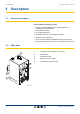
3. Description AFC 18 - AFC 24 - AFC 30 3 Description 3.1 General description Floor-standing condensing oil boiler 4 Heating only (Optional domestic hot water production in combination with a DHW tank). 4 High efficiency heating. 4 Low pollutant emissions. 4 Modulating oil burner preassembled and preset. 4 Stainless steel heating body. 4 Top of the range electronic DIEMATIC iSystem control panel. 4 Flue gas evacuation by a forced flue or chimney type connection. 3.
AFC 18 - AFC 24 - AFC 30 3.3 3. Description Control panel Description of the keys A000866-A 3.3.1.
3. Description AFC 18 - AFC 24 - AFC 30 3.3.2.
AFC 18 - AFC 24 - AFC 30 3.
3. Description AFC 18 - AFC 24 - AFC 30 n System pressure bar 0 2 4 6 8 10 12 14 16 18 20 22 24 bar r j l M C002708-A p b AUTO x c g m t STD Pressure indicator: The symbol is displayed when a water pressure sensor is connected. 4 Flashing symbol: The water pressure is insufficient. 4 Steady symbol: The water pressure is sufficient.
AFC 18 - AFC 24 - AFC 30 3. Description 3.3.3. 0 4 6 8 10 12 14 16 #MEASURES #CHOICE TIME PROG. #TIME PROGRAM #SETTING c #TIME .DAY r v bar 2 18 20 22 24 a 1 2 1 2 p b AUTO x c g m ( ' r j Browsing in the menus 1. To select the desired menu, turn the rotary button. 2. To access the menu, press the rotary button. To go back to the previous display, press the key j. L t STD C002220-B-04 0 2 4 6 8 10 12 14 16 18 20 CURRENT PROG.B CURRENT PROG.
4. Operating the appliance AFC 18 - AFC 24 - AFC 30 4 Operating the appliance 4.1 Putting the appliance into operation 1. Turn on the boiler using the on/off switch. 8 20 22 24 0 l C003159-A 0 v bar c 1 2 1 2 2 4 6 8 10 12 14 16 18 20 22 2. The first time the boiler is powered up, the LANGUAGE menu is displayed. Select the desired language by turning the rotary button. 3. To confirm, press the rotary button. 4.
AFC 18 - AFC 24 - AFC 30 4. Operating the appliance User level - Menu #MEASURES Parameter Description Unit Room temperature of circuit C °C BOILER TEMP Water temperature in the boiler °C PRESSURE Water pressure in the installation bar (MPa) OIL PRESSURE Injection nozzle oil pressure bar (MPa) Water temperature in the DHW tank °C Instant hot water temperature °C Water temperature in the storage tank °C ROOMTEMP.C (1) WATER TEMP. (1) (1) TEMP DHW INST STOR.TANK.TEMP (1) SWIMMING P.
4. Operating the appliance 4.3 AFC 18 - AFC 24 - AFC 30 Changing the settings 4.3.1. Setting the set point temperatures To set the various heating, DHW and swimming pool temperatures, proceed as follows: 1. Press the C key. 2. To select the desired parameter, turn the rotary button. 3. To modify the parameter, press the rotary button. To go back to the previous display, press the key j. 4. To modify the parameter, turn the rotary button. 5. To confirm, press the rotary button.
AFC 18 - AFC 24 - AFC 30 4. Operating the appliance 4.3.2. Selecting the operating mode To select an operating mode, proceed as follows: 1. Press the MODE key. 2. To select the desired parameter, turn the rotary button. 3. To modify the parameter, press the rotary button. To go back to the previous display, press the key j. 4. To modify the parameter, turn the rotary button. 5. To confirm, press the rotary button. MODE To cancel, press key h.
4. Operating the appliance AFC 18 - AFC 24 - AFC 30 4.3.3. Forcing domestic hot water production To force domestic hot water production, proceed as follows: 1. Press the r key. 2. To select the desired parameter, turn the rotary button. 3. To modify the parameter, press the rotary button. To go back to the previous display, press the key j. 4. To modify the parameter, turn the rotary button. 5. To confirm, press the rotary button. MODE To cancel, press key h.
4. Operating the appliance AFC 18 - AFC 24 - AFC 30 4.3.5. Setting the time and date 1. To access user level: Press the > key. 0 2 4 6 8 10 12 14 16 18 20 22 24 2. Select the menu #TIME .DAY. SUNDAY 11:45 v bar c Turn the rotary button to scroll through the menus or modify a value. 4 Press the rotary button to access the selected menu or confirm a value modification. ¼For a detailed explanation of menu browsing, refer to the chapter: "Browsing in the menus", page 14.
AFC 18 - AFC 24 - AFC 30 4. Operating the appliance User level - Menu #CHOICE TIME PROG. Parameter Adjustment range Description CURRENT PROG.A P1 / P2 / P3 / P4 Comfort programme activated (Circuit A) CURRENT PROG.B P1 / P2 / P3 / P4 Comfort programme activated (Circuit B) CURRENT PROG.C P1 / P2 / P3 / P4 Comfort programme activated (Circuit C) 4.3.7. Customising a timer programme 1. To access user level: Press the > key. 0 2 4 6 8 10 12 14 16 18 20 22 2.
AFC 18 - AFC 24 - AFC 30 0 v bar c 1 2 1 2 2 4 6 8 10 12 14 4. Operating the appliance 16 18 PROG P2 C Mo Tu We Th Fr "Select the days to program" r p b AUTO x c g m ( ' r 20 Sa j 22 24 a Su L t STD 6. b: Day selection Press key b / v until the symbol b is displayed. Turn the rotary button to the right to select the day(s) desired. v: Cancelling the day selection Press key b / v until the symbol v is displayed.
AFC 18 - AFC 24 - AFC 30 4. Operating the appliance User level - Menu #TIME PROGRAM Day Comfort periods / Filling enabled: P1 P2 _______________ P3 _______________ P4 _______________ _______________ TIME PROG.DHW Monday Tuesday Wednesday Thursday Friday Saturday Sunday TIME PROG.AUX Monday Tuesday Wednesday Thursday Friday Saturday Sunday 4.4 Installation shutdown If the central heating system is not used for a long period, we recommend switching the boiler off. 4 Switch the On/Off switch to Off.
AFC 18 - AFC 24 - AFC 30 4. Operating the appliance CAUTION 4 4 The antifreeze protection does not function if the appliance is switched off. The integrated protection system only protects the boiler, not the installation. To protect the installation, set the appliance to HOLIDAYS mode. The HOLIDAYS mode protects: 4 The installation if the outside temperature is lower than 3°C (factory setting).
5. Checking and maintenance AFC 18 - AFC 24 - AFC 30 5 Checking and maintenance 5.1 General instructions The boiler does not require a lot of maintenance. Nevertheless, we recommend having the boiler inspected and serviced at regular intervals. 4 Maintenance and cleaning of the boiler must be carried out at least once a year by a qualified technician. 4 Have the flues swept at least once a year or more, depending on the regulations in force in your country.
5. Checking and maintenance AFC 18 - AFC 24 - AFC 30 4 Carry out a visual check for the presence of any water leaks. T001507-B 4 Open and close the radiator valves several times a year (this prevents the valves from seizing up). 4 Clean the outside of the boiler using a damp cloth and a light detergent. 1 2 CAUTION 3 4 T000181-B 5.3 Only a qualified professional is authorised to clean the inside of the boiler. Filling the system 1.
5. Checking and maintenance AFC 18 - AFC 24 - AFC 30 5. To add water, use the filling pipe with a valve fitting, a cloth and a venting spanner. C003835-A 6. Connect the filling tube to a (cold) water tap. T000846-A 7. Eliminate the air from the filling tube. Slowly fill the tube with water. Hold the end of the tube up, above a bucket. Turn off the tap as soon as water runs out of the pipe. C003836-A 8. Unscrew the plug from the filling/draw-off valve.
5. Checking and maintenance AFC 18 - AFC 24 - AFC 30 9. Attach the tube to the filling/draw-off valve. Firmly tighten the nut on the filling tube. 10.Open the filling/draw-off valve on the heating system. 11.Open the running water tap. 12.Check the water pressure in the installation shown on the control panel display. 13.Close the water tap when the water pressure reaches 2 bar. C003837-A 14.Close the filling/draw-off valve on the heating system.
5. Checking and maintenance AFC 18 - AFC 24 - AFC 30 6. Bleed the radiators. Start with the lower floors. 5 3 4 1 2 T000854-A 7. Open the bleed connection using the bleed key provided whilst keeping a rag pressed against the connection. T000217-A 8. Wait until water comes out of the bleed valve and then close the bleed connection. CAUTION The water may still be hot. 9. Switch on the boiler. 10.Check whether the pressure in the installation is still sufficient.
AFC 18 - AFC 24 - AFC 30 5. Checking and maintenance 11.Set the heating set point. 5.5 Draining the installation It may become necessary to empty the water from the heating system when the radiators have to be replaced, should there be a major water leak or a risk of frost. To do this, proceed as follows: 1. Open the valves on all radiators connected to the heating system. 1 2 3 4 T000181-B 2. Switch off the boiler electrical power supply. 3. Wait around 10 minutes until the radiators are cold.
6. Troubleshooting AFC 18 - AFC 24 - AFC 30 6 Troubleshooting 6.1 Anti-hunting When the boiler is in Anti-short-cycle operating mode, the symbol ? flashes. 1. Press the "?" key. The message Operation assured when the restart temperature will be reachednctionnement assuré lorsque la température de redémarrage sera atteinte} is displayed. This message is not an error message but an item of information. 6.
AFC 18 - AFC 24 - AFC 30 6. Troubleshooting Code Messages Description B04 BL.SMOKE.TEMP The maximum flue gas 4 temperature has been exceeded. If this message is generated 5 times in 24 hours, the boiler locks down in L30. Checking / solution B10 B11 BL.SC.IN.OPEN The BL inlet on the PCU PCB terminal block is open Contact the professional who takes care of maintenance of the appliance.
6. Troubleshooting AFC 18 - AFC 24 - AFC 30 Code Messages Description B28 BL.BAD.CONFIG An HL tank is detected whilst the 4 boiler cannot control it. This message disappears after 4 10 seconds if the boiler can control the HL tank Checking / solution Wait for 10 seconds to see whether the error persists Contact the professional who takes care of maintenance of the appliance B29 to B34 BL.
AFC 18 - AFC 24 - AFC 30 6.
6. Troubleshooting AFC 18 - AFC 24 - AFC 30 Code Faults Cause of the fault Description Checking / solution L30 DEF.FLUE GAS PRESSURE PCU The flue gas pressure switch opened 5 times in 24 hours. L31 DEF.SMOKE.TEMP PCU The maximal smoked temperature 4 is exceeded of 5 times in 24 hours. L32 DEF.OUTLET S.
AFC 18 - AFC 24 - AFC 30 6. Troubleshooting Code Faults Cause of the fault Description Checking / solution D05 OUTSI.S.FAIL. SCU Outside temperature sensor fault Bad connection Sensor fault Remarks: The boiler operates on BOILER 4 Contact the professional who takes care of MAX temperature. maintenance of the appliance The valve setting is no longer ensured but monitoring the maximum temperature of the circuit after the valve is ensured. Valves may be manually operated.
6. Troubleshooting AFC 18 - AFC 24 - AFC 30 Code Faults Cause of the fault Description Checking / solution D27 PCU COM.FAIL SCU Communication failure between the SCU and PCU PCBs D37 TA-S SHORT-CIR SCU 4 Contact the professional who takes care of maintenance of the appliance The Titan Active System® is short-circuited 4 Contact the professional who takes care of maintenance of the appliance Remarks: Domestic hot water production has stopped but can nonetheless be restarted using key r.
AFC 18 - AFC 24 - AFC 30 7. Technical specifications 7 Technical specifications 7.1 Technical specifications 7.1.1. Boiler specifications Test conditions: 4 CO2 of 12% at min output and 13% at max output with oil. 4 Maximum operating pressure - Primary circuit (heating water): 3 bar (0.3 MPa) 4 Maximum operating temperature: 85 °C 4 Boiler temperature: Adjustable from 30 to 90 °C 4 Safety thermostat: 105 °C 4 Min flow temperature: 20°C 4 Min.
7. Technical specifications AFC 18 - AFC 24 - AFC 30 Boiler AFC 18 Minimum power AFC 24 Full power Minimum power AFC 30 Full power Minimum power CO2 content (Minimum output - Start- % up output - Maximum output 12 - 13 - 13 12 - 13 - 13 12 - 13 - 13 Nominal water flow rate at Pn (50/30 °C) ΔT = 20K m3/h 0.773 1.032 1.
8. Energy savings AFC 18 - AFC 24 - AFC 30 8 Energy savings 8.1 Energy-saving advice 4 Keep the room in which the boiler is installed well ventilated. 4 Do not block ventilation outlets. 4 Do not cover the radiators. Do not hang curtains in front of the radiators. 4 Install reflective panels behind the radiators to prevent heat losses. 4 Insulate the pipes in rooms that are not heated (cellars and lofts). 4 Close the radiators in rooms not in use. 4 Do not run hot (or cold) water pointlessly.
AFC 18 - AFC 24 - AFC 30 9. Warranty 9 Warranty 9.1 General You have just purchased one of our appliances and we thank you for the trust you have placed in our products. Please note that your appliance will provide good service for a longer period of time if it is regularly checked and maintained. Your installer and our customer support network are at your disposal at all times. 9.
AFC 18 - AFC 24 - AFC 30 09/01/2014 - 300026440-001-03 9.
DE DIETRICH THERMIQUE S.A.S +49 (0)25 72 / 9161-0 +49 (0)25 72 / 9161-102 info@remeha.de DE DIETRICH THERMIQUE Iberia S.L.U. www.dedietrich-calefaccion.es ES C/Salvador Espriu, 11 08908 L’HOSPITALET de LLOBREGAT +34 935 475 850 info@dedietrich-calefaccion.es 129164, Россия, г. Москва Зубарев переулок, д. 15/1 Бизнес-центр «Чайка Плаза», офис 309 +7 (495) 221-31-51 DE DIETRICH SERVICE www.dedietrich-heiztechnik.com Freecall 0800 / 201608 IT BDR Thermea (Czech republic) s.r.o www.dedietrich.