Warming drawer WDU/WDV & WDUI/WDVI models Chauffe-plats Modèles WDU/WDV & WDUI/WDVI Installation instructions and User guide Instructions d’installation et Guide d’utilisation US CA
A MESSAGE TO OUR CUSTOMERS Thank you for selecting this DCS warming drawer. Because of its unique features, we have developed this manual. It contains valuable information on how to properly install, use and maintain your new warming drawer for years of safe and enjoyable use. For your convenience, product questions can be answered by a Fisher & Paykel Customer Care Representative by phone:1-888-936-7872, or email: customer.care@fisherpaykel.com.
2 US CA TABLE OF CONTENTS SAFETY PRACTICES AND PRECAUTIONS 3 INSTALLATION INSTRUCTIONS Specifications Mounting Installation Custom Panel Installation (WDUI/WDVI) Cabinet Installation 6 7 9 10 FEATURES 12 OPERATING INSTRUCTIONS 13 CARE AND MAINTENANCE Cleaning the warming drawer Removing the drawer Replacing the drawer 14 15 16 TEMPERATURE SETTINGS 17 WARRANTY AND SERVICE 18
SAFETY PRACTICES AND PRECAUTIONS 3 US CA READ AND UNDERSTAND THESE PRECAUTIONS ■ Read these precautions and the entire manual thoroughly before installation or use. This will help to reduce the risk of fire, electric shock, or injury to persons. ■ Remove all packaging materials from your appliance. ■ Install according to instructions. ■ Be sure to have a qualified service technician install and ground this appliance. ■ Plug into rated outlet: 120 Volts AC, 5 amp min., 15 amp maximum circuit requirement.
4 SAFETY PRACTICES AND PRECAUTIONS US CA ■ Never heat unopened containers, a build up of pressure may cause the container to burst. ■ Grease is flammable, avoid letting grease deposits collect in the warming drawer, clean up spillage. ■ 120 Volts AC, 5 amp min., 15 amp maximum circuit requirement. ■ DO NOT use water on grease fires. Turn OFF the warming drawer, then smother the fire with baking soda or use a dry chemical or foam-type fire extinguisher.
5 US CA
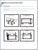
6 INSTALLATION INSTRUCTIONS US CA SPECIFICATIONS The cabinet depth from the outer edge of the face frame to the inside back of the cabinet or wall should be at least 24” (see Fig. 1). The warming drawer should be installed into a base cabinet with minimum outside dimensions of 13-1/4” high by 30” wide by 24” deep. Power supply required: 120Volts AC; 5 amp min., 15 amp maximum circuit requirement. CUT OUT DIMENSIONS WARMING DRAWER DIMENSIONS (FRONT VIEW) 1-1/2" min.
INSTALLATION INSTRUCTIONS 7 US CA MOUNTING INSTALLATION The lower rear corners of the cabinet need to provide proper support to the back of the warming drawer and the anti-tip mounting clips. A 120 volt AC outlet should be located no further than 36 inches from the back center of the warming drawer. The bottom rear section of the cabinet should be made of solid plywood or two 2x4 beams. It holds the anti-tip mounting clips and supports the weight of the warming drawer, which is 90 lbs. (see Figs.
8 INSTALLATION INSTRUCTIONS US CA Slot Slot 20" Center line to center line for mounting clips for WDU-30 WDUI Power cord Fig. 6 1-1/2” mounting screws Fig.
INSTALLATION INSTRUCTIONS 9 US CA CUSTOM PANEL INSTALLATION OF THE INTEGRATED WARMING DRAWER (WDUI/ WDVI) STEP 1 Remove drawer as per instructions (see section ‘Care and maintenance’). STEP 2 Check the dimensions of the front face (see Fig. 8). STEP 3 Cut the custom panel to the desired dimensions, knowing that the panel must cover the paper front template plus 1/8” on all four sides for a good presentation.
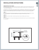
10 INSTALLATION INSTRUCTIONS US CA CABINET INSTALLATION DOUBLE wall oven and warming drawer Installation SINGLE wall oven and microwave and warming drawer Installation microwave cut-out double wall oven cutout 10 + – 1/16" 11-3/16" single wall oven cutout 10 + – 1/16" 11-3/16" warming drawer cutout** warming drawer cutout** 25-3/4 –+1/16" Fig. 9 15-3/4" 25-3/4 –+1/16" 18-3/4" Fig.
11 US CA
12 FEATURES US CA * Vent holes Thermostat control knob * Moist/ crisp knob Removable stainless steel tray * Power indicator lens Power indicator light Model number and serial number location on inside panel Stainless steel drawer Handle not illustrated * Not available on fully integrated model (WDUI/WDVI). Fig.
OPERATING INSTRUCTIONS 13 US CA OPERATIONAL GUIDE The warming drawer is designed to keep previously cooked foods at a safe, warm temperature, for extended periods of time, when operated correctly. It is not designed to cook or reheat food. The warming drawer should be preheated according to the chart below prior to inserting the food to be warmed. Food may be kept up to two hours in the warming drawer.
14 CARE AND MAINTENANCE US CA CLEANING THE WARMING DRAWER ■ Be careful cleaning any part of this appliance, particularly the drawer box and back of the drawer face. All parts of the drawer can be cleaned with a hot soapy damp cloth, rinsed, dried and buffed with a heavy pile cloth. Always try this first, as it is the mildest cleaning procedure. ■ Be sure the warming drawer is turned off and the appliance is cool before using any type of aerosol cleaner on or around the appliance.
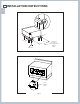
CARE AND MAINTENANCE 15 US CA REMOVING THE DRAWER Turn the unit off. Be sure the drawer is cool and no food items or trays are in the drawer. Never attempt to remove the drawer while the unit is on or warm. 1. To remove the drawer, first remove plates, trays, etc., from the drawer. 2. Pull the drawer open towards you all the way until it reaches the stop position (Fig. 13). 3. Unlock the drawer by lifting up the tab on the left hand side (Fig. 14) and pressing down the tab on the right hand side (Fig.
16 CARE AND MAINTENANCE US CA REPLACING THE DRAWER WARNING With the drawer removed, the heating element is exposed. Never turn the unit on while the drawer is removed. Never let children play near or touch the warming drawer while it is not safely installed. Push the slides back into the cabinet while the drawer is removed to prevent accidents. 1. To reinstall the drawer, push the slides fully inside. 2. Position the drawer in front of the cavity and align the slides (Fig. 17). 3.
TEMPERATURE SETTINGS 17 US CA SUGGESTED TEMPERATURES TO KEEP FOODS HOT FOOD TEMPERATURE SLIDE KNOB COVERED/ POSITION UNCOVERED Beef** Rare Low Moist Covered Medium Med Moist Covered Well Done Med Moist Covered High Crisp Uncovered Proofing Moist Covered Casseroles Med Moist Covered Chips High Crisp Uncovered Cooked Cereal Med Moist Covered Eggs Med Moist Covered Fish, Seafood Med Moist Covered Fried Foods (all) High Crisp Uncovered Fruit Med Moist Covere
18 WARRANTY AND SERVICE US CA Before you call for service or assistance ... Check the things you can do yourself. Refer to the installation instructions and your user guide and check that: 1 2 your product is correctly installed you are familiar with its normal operation. If after checking these points you still need assistance or parts, please refer to the Service & Warranty document for warranty details and your nearest Authorized Service Center, Customer Care, or contact us through our website www.
19
20 US CA (FR) À L’INTENTION DE NOS CLIENTS Nous vous remercions d’avoir choisi ce chauffe-plats DCS. Nous avons conçu ce manuel pour expliquer les fonctions uniques de cet appareil. Il contient des informations extrêmement utiles sur la façon correcte d’installer et de faire fonctionner votre nouveau chauffe-plats et d’en faire l’entretien. Vous pourrez ainsi en profiter pendant des années en toute sécurité.
TABLE DES MATIÈRES 21 MESURES DE SÉCURITÉ ET DE PRÉCAUTION 22 US CA (FR) INSTRUCTIONS DE MONTAGE Spécifications Montage et Installation Installation de Panneau Personnalisée (WDUI/WDVI) Préparation des Armoires 24 25 27 28 CARACTERISTIQUES DU CHAUFFE-PLATS 29 GUIDE OPÉRATIONNEL 30 INSTRUCTIONS D’ENTRETIEN Nettoyage du chauffe-plats Retrait du tiroir Replacement du tiroir 31 32 33 RÉGLAGES DE TEMPÉRATURE 34 GARANTIE ET SERVICE 35
22 US CA (FR) MESURES DE SÉCURITÉ ET DE PRÉCAUTION VEUILLEZ LIRE ET BIEN ASSIMILER CES CONSIGNES ■ Veuillez lire attentivement ces consignes et tout le manuel d’installation avant d’installer ou d’utiliser votre nouvel appareil. Ceci vous permettra de réduire les risques d’incendie, de chocs électriques ou de blessures. ■ Retirez tout le matériel d’emballage de l’appareil. ■ Procédez à l’installation conformément aux instructions. ■ Confiez la mise à la terre de l’appareil à un technicien qualifié.
MESURES DE SÉCURITÉ ET DE PRÉCAUTION AVERTISSEMENT Cet appareil est conçu pour réchauffer les aliments. Pour des raisons de sécurité, n’utilisez jamais le chauffe-plats pour chauffer une pièce. ■ Comme pour tout appareil de cuisson ou de chauffage, ne laissez jamais le chauffe-plats sans surveillance quand vous réchauffez de la nourriture, car il y a risque d’incendie.
24 US CA (FR) INSTRUCTIONS DE MONTAGE SPÉCIFICATIONS La profondeur du boîtier, à partir de la bordure extérieure de la face avant jusqu’au fond du boîtier ou au mur, doit mesurer 61 cm (24 po) minimum (voir Fig.1). Le chauffe-plats doit être installé dans un boîtier dont les dimensions extérieures minimum doivent être de 33,5 cm (13-1/4 po) de haut sur 76 cm (30 po) de large sur 61 cm (24 po) de profondeur. Alimentation requise : 120 V c.a.; 5 A min., 15 A maximum requis.
INSTRUCTIONS DE MONTAGE 25 MONTAGE ET INSTALLATION US CA (FR) Les coins inférieurs arrière du boîtier doivent soutenir correctement l’arrière du chauffe-plats et les fixations antibasculement. Une prise c.a. de 120 V doit être située à moins de 92 cm (36 po) du centre arrière du chauffe-plats. La section arrière inférieure de l’élément doit être fabriquée en contreplaqué plein ou de deux poutres 2 x 4.
26 INSTRUCTIONS DE MONTAGE US CA (FR) 50,8 cm (20 po) cordon d’alimentation De la ligne médiane à la ligne médiane pour les fixations WDU-30 WDUI Fig. 6 3,8 cm (1-1/2 po) vis de montage Fig.
INSTRUCTIONS DE MONTAGE 27 INSTALLATION DE PANNEAU PERSONNALISÉE DU TIROIR CHAUFFANT INTÉGRÉ (WDUI/WDVI) ÉTAPE 1 Retirez le chauffe-plats conformément aux instructions. (Voir la section ‘Instructions d’entretien’.) ÉTAPE 2 Vérifiez les dimensions du gabarit devant. (Voir Fig. 8.) ÉTAPE 3 Découpez le panneau fait sur mesure selon les dimensions requises, sachant que le panneau doit recouvrir le gabarit avant et dépasser de 3,2 mm (1/8 po) sur les quatre côtés afin de soigner l’aspect d’ensemble.
28 US CA (FR) INSTRUCTIONS DE MONTAGE PRÉPARATION DES ARMOIRES Four double et installation de chauffe-plats Four simple, micro-ondes et installation de chauffe-plats découpe de micro-ondes découpe de four double découpe de four simple 28,4 cm (11-3/16 po) 25,4 cm + – 1,6 mm (10 + – 1/16 po) découpe de chauffe-plats** 28,4 cm (11-3/16 po) 25,4 cm + – 1,6 mm (10 + – 1/16 po) découpe de chauffe-plats** 47,6 cm (18-3/4 po) 40,0 cm (15-3/4 po) 65,4 cm –+ 1,6 mm (25-3/4 –+1/16 po) 65,4 cm –+ 1,6 mm (25
CARACTÉRISTIQUES DU CHAUFFE-PLATS * Trous de ventilation 29 US CA (FR) Bouton de réglage du thermostat * Bouton humide/croustillant Plateau en acier inoxydable amovible * Lentille du voyant d'alimentation Voyant d'alimentation Tiroir en acier inoxydable Poignée non illustrée Fig.
30 US CA (FR) GUIDE OPÉRATIONNEL GUIDE OPÉRATIONNEL Le chauffe-plats est conçu pour garder les aliments cuits à une température chaude sécuritaire, pendant de longues périodes, à condition d’être utilisé correctement. Il n’est pas conçu pour cuire ou réchauffer les aliments. Le chauffe-plats doit être préchauffé tel qu’indiqué au tableau ci-dessous avant d’y placer des aliments à réchauffer. Les aliments peuvent être gardés dans le chauffe-plats jusqu’à deux heures.
INSTRUCTIONS D’ENTRETIEN 31 NETTOYAGE DU CHAUFFE-PLATS US CA (FR) ■ Faites attention quand vous nettoyez cet appareil, en particulier le boîtier du tiroir et l’arrière de la face du tiroir. Toutes les parties de l’appareil peuvent être nettoyées avec linge humide savonneux chaud, puis rincées, séchées et bien polies à l’aide d’un tissu à poils épais. Essayez cela en premier, c’est la façon la plus douce de le nettoyer.
32 US CA (FR) INSTRUCTIONS D’ENTRETIEN RETRAIT DU CHAUFFE-PLATS Éteindre l’unité. Assurez-vous que le chauffe-plats est froid et qu’aucun aliment ni plateau ne se trouve à l’intérieur. N’essayez jamais de retirer le tiroir lorsque l’appareil est allumé ou chaud. 1. Pour retirer le tiroir, retirez d’abord les plats, plateaux, etc. du tiroir. 2. Ouvrez le tiroir complètement jusqu’à ce qu’il s’arrête (Fig.13). 3. Déverrouiller le tiroir en relevant la languette sur le côté gauche (Fig.
INSTRUCTIONS D’ENTRETIEN 33 REPLACEMENT DU TIROIR US CA (FR) AVERTISSEMENT Lorsque le tiroir est retiré, l’élément chauffant est exposé. N’allumez jamais l’appareil en l’absence du tiroir. Ne laissez jamais les enfants jouer à proximité du chauffe-plats ou le toucher lorsqu’il n’est pas installé de façon sécuritaire. Pour éviter tout risque d’accident, repoussez les glissières dans le boîtier lorsque le tiroir a été retiré. 1.
34 US CA (FR) RÉGLAGES DE TEMPÉRATURE TEMPÉRATURES SUGGÉRÉES POUR GARDER LES ALIMENTS CHAUDS ALIMENTS TEMPÉRATURE GLISSEZ LE BOUTON DE POSITION RECOUVERT/ DÉCOUVERT Saignant Bas Humide Recouvert Demi-saignant Moyen Humide Recouvert À point Moyen Humide Recouvert Bacon Haut Croustillant Découvert Pâte à pain Apprêt Humide Recouvert Casseroles Moyen Humide Recouvert Croustilles Haut Croustillant Découvert Céréales cuites Moyen Humide Recouvert Œufs Moyen Humide Recouve
GARANTIE ET SERVICE 35 Avant d'appeler pour demander une réparation ou de l'assistance... US CA (FR) Vérifiez les points que vous pouvez contrôler vous-même. Consultez les instructions d’installation et le guide de l’utilisateur pour vous assurer que : 1 2 votre produit est installé correctement. vous êtes familier avec son fonctionnement normal.
www.dcsappliances.com Copyright © Fisher & Paykel 2014. All rights reserved. The product specifications in this booklet apply to the specific products and models described at the date of issue. Under our policy of continuous product improvement, these specifications may change at any time. You should therefore check with your Dealer to ensure this booklet correctly describes the product currently available. Droits réservés © Fisher & Paykel 2014.