
Installation guide

Installation
5
2.5 AUX Power Wiring
The control panel can provide a maximum of 700mA of current for modules, powered detectors, relays, LED’s etc. If the total current required exceeds
700mA an additional power supply is required (e.g.,PC5200, PC5204). See list below.
NOTE: AUX Output voltage: 12VDC, -15%/+10% when Input Voltage is between 85%-110% of rated value and output current between 0.0A - 0.5A
max. Refer to the list of Compatible Devices on page 1 and/or the Reference Manual for the current draw of individual devices
2.6 PGM Wiring
PGMs switch to ground when activated by control panel.
Connect the positive side of the device to be activated to the AUX+
Terminal. Connect the negative terminal to the PGM.
current output is as follows
• PGM 1, 3, 4............................................................................... 50mA
• PGM 2..................................................................................... 300mA
For currents levels greater than 300mA a relay is
required. PGM2 can also be used for 2-wire smoke
detectors.
NOTE: Use SEOL resistors on Fire Zones ONLY.
PGM 1, LED output with current limiting resistor and
Optional Relay driver output
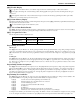
2-wire Smoke Detectors Initiating Circuit
• Style B (Class B), Supervised, Power Limited
• DC Output Voltage........................................................9.8-13.8 VDC
• Detector Load ............................................................... 2mA (MAX)
• Single-end-of-line (SEOL) Resistor .........................................2200Ω
• Loop Resistance.............................................................. 24Ω (MAX)
• Standby Impedance..................................................... 1020Ω ( Ν Ο Μ)
• Alarm Impedance.......................................................... 570Ω (MAX)
• Alarm Current.............................................................. 89mA (MAX)
2-wire Smoke Detectors 4-wire Smoke Detectors
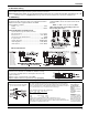
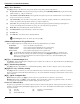
2.7 Telephone Line Wiring
Wire the telephone connection terminals (TIP, Ring, T-1, R-1) to an RJ-
31x Connector as indicated. Use 26 AWG wire minimum for wiring.
For connection of multiple devices to the telephone line, wire in the
sequence indicated.
Telephone format is programmed in section [350].
Telephone Call Directions are programmed in section [351]-[376].
2.8 Ground 2.9 Battery 2 . 1 0 A C W i r i n g
Ground Installation
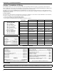
In accordance with EN5013-1 Standard for a Power Supply Type A rated for Grade 2 Sys-
tems, battery standby time required in the event of prime power source failure shall be
12hrs (min.). The table below is a guide indicating maximum loads for the standby times
shown. Load includes AUX+/-, Keybus (Red, Blk), and PGM 1-4 and modules (see table at
front of this publication), it does not include a battery safety margin
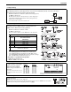
Battery Charging Current ma (4ah, 7ah batteries)
Batt size 4hr 12Hr 24Hr 36Hr
4Ah 500mA 220mA - -
7Ah 500mA 480mA 150mA -
14Ah - 500mA 480mA 280mA
24Ah - - 500mA 500mA
Program Section [701] Opt[7] to ON, if 14AH or 24AH battery is used.
NOTE: Replace batteries every 3-5 years, If two batteries are required to meet the
standby time, use DSC Enclosure Model Power UC1. Battery capacity will deteriorate with
age and number of charge/discharge cycles.
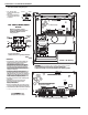
AC Wiring
Power Supply: In
accordance with
EN50131-1, Type A,
Grade 2
Primary: 220-240VAC/
50Hz/0.2A
Secondary: 16.5VAC/
40VA min.
WARNING!: Incorrect
conenction of batteries
may result in battery rup-
ture or fire hazard. Do
NOT allow metal objects
to connect the positive
and negative terminals.
RM-1/RM-2 POWER LOOP
SUPERVISORY RELAY
DSC FSA-210C Series
FSA-210C
FSA-210CT
FSA-210CS
FSA-210CST
FSA-210CLST
FSA-210CR
FSA-210CRT
FSA-210CRS
FSA-210CRST
FSA-210CLRST
FSA-410C
FSA-410CT
FSA-410CS
FSA-410CST
FSA-410CLST
FSA-410CR
FSA-410CRT
FSA-410CRS
FSA-410CRST
FSA-410CLRST
DSC FSA-410C Series
T-1
R-1
TIP
RING
RJ-31X
Tighten nut to break paint and make
good connection to the cabinet