
Installation guide

PowerSeries - PC1616/PC1832/PC1864
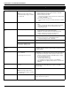
Trouble Cause Troubleshooting
Trouble [1] Service Required Press [1] to determine specific trouble
[1] Low Battery Main panel battery less than 11.1VDC
NOTE: This trouble condition will not
clear until the battery voltage is 11.8VDC
min., under load.
NOTE: If battery is new allow 1 Hr. for battery to charge.
• Verify voltage measured across AC terminals is 16-18 VAC.
Replace transformer if required.
• Disconnect battery wire leads
• Verify battery charging voltage measured across battery leads
= 13.70 - 13.80 VDC.
• Connect battery, remove AC power
• Verify measured voltage across battery terminals is 12.5VDC
min.
[2] Bell Circuit Bell+, Bell-...Open Circuit • Disconnect Bell-/Bell+ wire leads, measure resistance of wire
leads.
• Open circuit indicates break in wiring or defective siren/bell
• Jumper Bell+, Bell- with 1K resistor (Brown, Black, Red)
• Verify trouble clears
[3] General System Trou-
ble
PC5204 Output#1 Open Circuit • If Output#1 is unused: Ensure that terminals O1, AUX are
jumpered with 1K resistor (Brown, Black, Red)
• If Output #1 is used: Disconnect wire leads from O1, AUX
terminals, measure the resistance of the wire leads
• Open circuit indicates a break in the wiring
PC5204 AUX • Verify voltage measured across AC input terminals is 16-18VAC.
• Disconnect all connections to PC5204 AUX terminal.
• Verify AUX voltage is 13.70 - 13.80 VDC.
Printer connected to PC5400 offline Verify printer operation (out of paper, paper jam etc.)
T-Link Network Fault present
T-Link Receiver Trouble present
T-Link Interface Trouble present
Refer to the T-Link TL150/250/350 Installation Manual for details.
[4] General System
Tamper
Tamper input on module(s) open circuit Short tamper terminal to COM terminal on unused modules connected
to KEYBUS (PC5100, PC5108, PC5200, PC5204, PC5208, PC5320,
PC5400, PC5700).
[5] Module Supervision Panel does not communicate with mod-
ule(s) on KEYBUS
Keypad assigned to incorrect slot.
Modules are immediately enrolled and supervised when detected on
the KEYBUS. If a module has been removed, or if the slot assignment
of a keypad has been changed, module supervision must be reset.
• View the event buffer (via DLS or LCD5500 keypad) to identify
the specific module(s) in trouble
• To reset module supervision:
• Enter Program Section [902].
•Press [#] (wait 1 minute for panel to scan KEYBUS).
• Enter Program Section [903] to identify modules connected to the
KEYBUS.
[6] RF Jam Detected Wireless Receiver - excessive noise
detected.
Check for external 433MHZ signal sources
To disable RF Jam: enable Option [7] in program section [804]
subsection [90].
[7] PC5204 Low Battery PC5204 battery less than 11.5VDC
NOTE: This trouble condition will not
clear until the battery voltage is 12.5VDC
min., under load.
See [1] Low Battery above
[8] PC5204 AC Failure No AC at PC5204 AC inputs Verify voltage measured across AC terminals is 16-18VAC.
Replace transformer if required.