
Installation guide

PowerSeries - PC1616/PC1832/PC1864
4
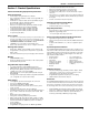
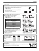
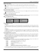
PC1616/1832/1864 Wiring Diagram
CON1
BA T+B AT -
1. Inser t
S
tand off into cabinet
mounting hole in the desired location.
Snap-in-place .
2. P osition circuit board mounting holes
ov er standoffs .P ress fir mly on board
to snap-in-place .
IMPO RT ANT !
Minimum 1/4" (6.4mm) separation
must be maintained at all points between
BA TTER Y/A CW IRING and all other
wi ri ng connections
FUSE
TB-2
AC AC RED BLK YEL GRN Z1 COM Z2 Z3 COM Z4 Z5 COM Z6 Z7 COM Z8
A UX+ BELL+
A UX- BELL-
PGM1 PGM3
EGND
TI PT -1
PGM2 PGM4
RING R- 1
DSC
220
220
U A503
PC-LINK
No. 14 AW G o rs maller conductor
Ty e W rap s (not supplied) recommended
Internally Connected
PC1864
Onl y
PC1864
PC1832
Onl y
PC1616/1832/1864
AC in
(Line)
AC in
(Neut )
Tr a n sf ormer
(Neut )
Tr a n sf ormer
(Line)
To EGND on
Cont ro l Modul e
PE
FUSE
7 AHr
NO TE:
CE, AS/N7S v ersions
use (1) 7AHr Batter y Only
PC Board
Cabinet
Stand Of f
9 8 4 3 1
5
2
TB- 2
AC AC RED BLK YEL GRN Z1 COM Z2 Z3 COM Z4 Z5 COM Z6 Z7 COM Z8
A UX+ BELL+
A UX- BELL-
PGM1 PGM3
EGND
TIP T- 1
PGM2 PGM4
RING R-1
DS C
REV XX
220
220
U A503
CON1
BA T+BA T-
PC-LINK
Internally Connected
AUX+ and Keybus (Red) ar eI nternally Connected
To ta l current draw from Keyp ads, PGM Output s and
Aux circui ts must not exceed 500m a
PC1864
Onl y
PC1864
PC1832
Onl y
6
PC1616/1832/1864
10
16.5V /40V A
AC
IMPOR T ANT :
1.This equipment, Alar m Controller PC1616/1832/1864/ETC shall
be installed and used within an en vironment that pro vides the
pollution degree max 2 and ov er v oltages categor y II
NON HAZARDOUS LOCA TIONS , indoor only . The equipment is
FIXED and PERMANENTL Y CONNECTED and is designed to be
installed by ser vice persons only; [ser vice person is defined as a
person h
a ving the appropr iate technical training and e xper ience
necessar y to be aw are of hazards to which that person ma y be
e xposed in perf or ming a task and of measures to minimiz e the r isks
to that person or other persons .]
2.The connection to the mains supply must be made as per the local
author ities r ules and regu
lations: In the UK as per BS6701.
An appropr iate disconnect de vice must be pro vided as par t of the
b uilding installation. Where it is not possib le to rely on identification of
the NEUTRAL in the AC MAINS SUPPL Y, the disconnecting de vice
must disconnect both poles simultaneously (LINE and NEUTRAL).
The de vice shall disconnect the supply dur ing ser vicing.
3.The equipment enclosure must be s
ecured to the bu ilding str ucture
bef ore operation.
4.Inter nal wir ing must be routed in a manner that pre v ents:
- Excessiv e strain on wire and on ter minal connections;
- Loosening of ter minal; connections;
- Damage of conductor insulation
5.Disposal of the used batter ies shall be made according to the w aste
reco ve ry a
nd recycling regulations applicab le to the intended ma rk et .
6. Bef ore SER VICING, DISCONNECT the TELEPHONE CONNECTION.
See correspondin
g
Section NumberT e xt f or wir in
g
details .
7
Incorrect connections may result in PTC failure or improper operation.
Inspect wiring and ensure connections are correct be fo re appl ying po we r.
Do NO T r oute an y wiring o ver cir cuit boar ds. Maintain at least 1"(25.4mm) separation.
W ARNING:
High V oltage . Disconnect AC Po wer
and telephone lines bef ore servicing
W ARNING:
220 - 240V , 50/60Hz, 200m A
AC
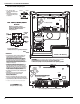
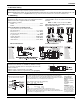
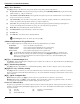
PC5003C Cabinet Sho wn
Use Model Po wer UC1 f or (2) Batter y Installations
CON1
BA T+B AT -
1. Inser t
S
tand off into cabinet
mounting hole in the desired location.
Snap-in-place .
2. P osition circuit board mounting holes
ov er standoffs .P ress fir mly on board
to snap-in-place .
IMPO RT ANT !
Minimum 1/4" (6.4mm) separation
must be maintained at all points between
BA TTER Y/A CW IRING and all other
wi ri ng connections
FUSE
TB-2
AC AC RED BLK YEL GRN Z1 COM Z2 Z3 COM Z4 Z5 COM Z6 Z7 COM Z8
A UX+ BELL+
A UX- BELL-
PGM1 PGM3
EGND
TI PT -1
PGM2 PGM4
RING R- 1
DSC
220
220
U A503
PC-LINK
No. 14 AW G o rs maller conductor
Ty e W rap s (not supplied) recommended
Internally Connected
PC1864
Onl y
PC1864
PC1832
Onl y
PC1616/1832/1864
AC in
(Line)
AC in
(Neut )
Tr a n sf ormer
(Neut )
Tr a n sf ormer
(Line)
To EGND on
Cont ro l Modul e
PE
FUSE
12VDC/ 7 Ah Battery
PC Board
Cabinet
Stand Of f
9 8 4 3 1
5
2
TB- 2
AC AC RED BLK YEL GRN Z1 COM Z2 Z3 COM Z4 Z5 COM Z6 Z7 COM Z8
A UX+ BELL+
A UX- BELL-
PGM1 PGM3
EGND
TIP T- 1
PGM2 PGM4
RING R-1
DS C
REV XX
220
220
U A503
CON1
BA T+BA T-
PC-LINK
Internally Connected
AUX+ and Keybus (Red) ar eI nternally Connected
To ta l current draw from Keyp ads, PGM Output s and
Aux circui ts must not exceed 500m a
PC1864
Onl y
PC1864
PC1832
Onl y
6
PC1616/1832/1864
10
16.5V /40V A
AC
IMPOR T ANT :
1.This equipment, Alar m Controller PC1616/1832/1864/ETC shall
be installed and used within an en vironment that pro vides the
pollution degree max 2 and ov er v oltages categor y II
NON HAZARDOUS LOCA TIONS , indoor only . The equipment is
FIXED and PERMANENTL Y CONNECTED and is designed to be
installed by ser vice persons only; [ser vice person is defined as a
person h
a ving the appropr iate technical training and e xper ience
necessar y to be aw are of hazards to which that person ma y be
e xposed in perf or ming a task and of measures to minimiz e the r isks
to that person or other persons .]
2.The connection to the mains supply must be made as per the local
author ities r ules and regu
lations: In the UK as per BS6701.
An appropr iate disconnect de vice must be pro vided as par t of the
b uilding installation. Where it is not possib le to rely on identification of
the NEUTRAL in the AC MAINS SUPPL Y, the disconnecting de vice
must disconnect both poles simultaneously (LINE and NEUTRAL).
The de vice shall disconnect the supply dur ing ser vicing.
3.The equipment enclosure must be s
ecured to the bu ilding str ucture
bef ore operation.
4.Inter nal wir ing must be routed in a manner that pre v ents:
- Excessiv e strain on wire and on ter minal connections;
- Loosening of ter minal; connections;
- Damage of conductor insulation
5.Disposal of the used batter ies shall be made according to the waste
reco ve ry a
nd recycling regulations applicab le to the intended ma rk et .
6. Bef ore SERVICING, DISCONNECT the TELEPHONE CONNECTION.
See correspondin
g
Section NumberT e xt f or wir in
g
details .
7
Inspect wiring and ensure connections are correct be fo re appl ying po we r.
Do NO T r oute an y wiring o ver cir cuit boar ds. Maintain at least 1"(25.4mm) separation.
W ARNING:
High V oltage . Disconnect AC Po wer
and telephone lines bef ore servicing
W ARNING:
220 - 240V , 50/60Hz, 200m A
AC
PC5003C Cabinet Sho wn
Use Model Po wer UC1 f or (2) Batter y Installations
41-56
7. Two batteries may be used to provide the required backup time.