
Installation guide

Installation
3
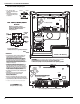
2.1 Keybus Wiring
The 4-wire KEYBUS (red, black, yellow and green) is the communication connection between the control panel and all modules.
The 4 KEYBUS terminals of all modules must be connected to the 4 KEYBUS terminals of the main control panel.
The following rules must be followed when wiring the Keybus:
• Minimum 22 AWG wire, maximum 18 AWG (2-wire twisted preferred
•Do NOT use shielded wire
• Modules can be home run, connected in series or can be T-tapped pro-
vided that the maximum wire distance from the control panel to any
module does not exceed 305m
• No more than 915m of wire can be used in total
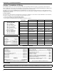
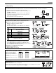
2.2 Zone Wiring
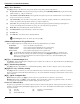
Zones can be wired for Normally Open, Normally Closed Contacts
with Single-end-of-line (SEOL) resistors or Double End-of-Line
(DEOL) resistors. Observe the following guidelines
• Minimum 22 AWG wire, maximum 18 AWG
•Do NOT use shielded wire
• Wire run resistance shall not exceed 100Ω. Refer to the chart below.
• Section [001-004] Selects Zone Definition
• Section [013] Opt [1] Selects Normally Closed or EOL resistors
• Section [013] Opt [2] Selects Single EOL or Double EOL resistors.
• Section [101]-[108] Opt [14], [15], [16] Selects Normally Closed Single
EOL or Double EOL for onboard zones (Zone 1-8)
Zone Status - Loop Resistance/Loop Status
• Fault - 0Ω (shorted wire/loop)
• Secure - 5600Ω (contact closed)
• Tamper - infinite (broken wire, open)
• Violated - 11,200Ω (contact open)
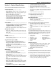
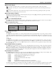
2.3 Zone Expanders
Zone expanders add zones in groups
of eight to the Alarm system. Module
jumpers J1,J2,J3 are required to
assign zones to these modules.
Jumper settings for PC5108v2 are
shown here.
• PC5108v1.0 supports first 32 zones only.
•
Do NOT use PC5108v1 &v2 on the same
panel.0
Module Zones
Jumpers
Assigned
J1 J2 J3
ON ON ON Zones Disabled
OFF ON ON Zones 09-16
ON OFF ON Zones 17-24
OFF OFF ON Zones 25-32
ON ON OFF Zones 33-40
OFF ON OFF Zones 41-48
ON OFF OFF Zones 49-56
OFF OFF OFF Zones 57-64
Refer to to the associated installation sheet for Jumper locations for the
PC5108v1
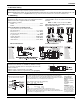
2.4 Bell Wiring
Bell Output Voltage: 12 VDC, 15%/+10% when input voltage is between 85-110% of rated value and output
current is 0.0A - 0.7A.
NOTE: Steady, Pulsed alarms are also supported.
The Bell output is supervised and power limited by 2A PTC. If unused, connect a 1000Ω resistor across Bell+
and Bell- to prevent the panel from displaying a trouble. See [][2].
CONTROL
PANEL
76m
76m
152m
152m
Burglary Zone Wiring Chart
Wire
Gauge
Maximum wire Length to
End-of-line Resistor
(feet/meters)
22 3000 / 914
20 4900 / 1493
19 6200 / 1889
18 7800 / 2377
Figures are based on maximum wiring
resistance of 100 ohms.
Normally Closed Loops - Do NOT use for UL Installations
Single End-of-Line Resistor Wiring
Double End-of-Line Resistor Wiring