
Installation guide

PowerSeries - PC1616/PC1832/PC1864
2
Section 2: Installation & Wiring
This Installation Guide provides the basic installation, wiring and programming information required to program the PowerSeries PC1616,
PC1832 and PC1864 control panels. This guide shall be used in conjunction with the PowerSeries PC1616/1832/1864 Reference Manual which
can be obtained from your local dealer or downloaded from the DSC web site at www.dsc.com.
This Product is in Conformity with EMC Directive 89/336/EEC based on results using harmonized standards in accordance with article 10(5),
R&TTE Directive 1999 Based on Following Annex III of the directive and LVD directive 73/23/EEC as amended by 93/68/EEC based on results
using Harmonized standards.
Technical Summary
This product meets the requirements of Class II, Grade 2 equipment as per EN50131-1:1997, TS50131-3:2003 and EN50131-6:1997 Standards.
This device is suitable for use in systems with the following notification options.
o A (use of two warning devices and internal dialer required
o B (self powered warning device and internal dialer required
o D (use of DSC model T-Link TL250 encrypted Ethernet communicator required.
Installation
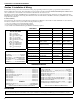
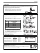
FEATURES
PC1616 PC1832 PC1864
OUT Of THE BOX
On-board Zones 6 8 8
Qty 1
Qty 1
Qty 1
Qty 1
Qty 2
Qty 1
Qty 4
Qty 16
Qty 1
Qty 1
Qty 1
Cabinet
PC Module
Installation guide
User manual
Cabinet Label
Cabinet Door Plug
Standoffs
5.6KΩ Resistors
2.2KΩ Resistor
1.0KΩ Resistor
Grounding Kit
Hardwired Zones 16 (1xPC5108) 32(3xPC5108) 64 (7xPC5108)
Wireless Zones 32 32 32
Keypad Zone Support
On-board PGM Outputs PGM 1 - 50mA
PGM 2 - 300mA
PGM 1 - 50mA
PGM 2 - 300mA
PGM 1, 3, 4 - 50mA
PGM 2 - 300mA
PGM Expansion 8x50mA (PC5208)
4x500 mA (PC5204)
8x50mA (PC5208)
4x500 mA (PC5204)
8x50mA (PC5208)
4x500 mA (PC5204)
Keypads 8 8 8
Partitions 2 4 8
SPECIFICATIONS
Temp Range ............................... 0°C-49°C
Humidity (Max) ............................ 93%R.H.
Power Supply......... 16.5VAC/40VA @60Hz
Current Draw (Panel)...........110mA (nom.)
Aux+ Output............ 11.1-12.6VDC/500mA
Bell Output.............. 11.1-12.6VDC/700mA
User Codes 47 + Master Code 71 + Master Code 94 + Master Codes
Event Buffer 500 Events 500 Events 500 Events
Transformer Required 16.5VAC/40VA 16.5VAC/40VA 16.5VAC/40VA
Battery Required 4Ah / 7Ah/14AHr 4Ah / 7Ah/14AHr 4Ah / 7Ah/14AHr
Bell Output 12V/700 mA (cont) 12V/700 mA (cont) 12V/700 mA (cont)
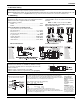
COMPATIBLE DEVICES
Keypads (
Backward compatible with all PowerSeries keypads) Modules
PK5500 Keypad ....................................................................... 125mA (max.)
PK5501 Keypad ....................................................................... 125mA (max.)
PK5508 LED Keypad ............................................................... 125mA (max.)
PK5516 LED Keypad ............................................................... 125mA (max.)
LCD5511 Fixed Message LCD Keypad .................................... 85mA (max.)
LED5511Z 8-zone LED Keypad .............................................. 100mA (max.)
RFK5500 Keypad..................................................................... 135mA (max.)
RFK5501 Keypad..................................................................... 135mA (max.)
RFK5508 Keypad..................................................................... 135mA (max.)
RFK5516 Keypad..................................................................... 135mA (max.)
Cabinets
PC5003C(removable door)............................................ 248x298x78mm
Model Power UC1 ...................................................... 315x 319x100mm
Refer to the Reference Manual for alternate control cabinets
T-Link TL-250/TL300...................................................... 275/350mA
PC5100 2-wire Interface........... 40mA plus devices to 170mA max.
PC5132-433 Wireless Receiver ........................................... 125mA
RF5108-433 Wireless Receiver ........................................... 125mA
PC5108 Zone Expander ......................................................... 30mA
PC5200 Power Supply ............................................................ 20mA
PC5204 Power Supply with 4 Programmable Outputs ........... 30mA
PC5208 Low Current Programmable Output Module ............. 50mA
PC5400 Printer/DVAC Module ............................................... 65mA
PC5401 Bi-Directional RS232 Module (Not UL Listed) .......... 65mA
Escort5580 Telephone Interface Module ............................. 130mA
Refer to the Reference Manual for additional devices.
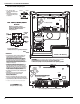
Begin the installation by mounting additional modules in the cabinet using the standoffs provided, then mount the cabinet in a dry protected area with
access to unswitched AC power. Install Hardware in the sequence indicated in the following pages. Do NOT apply power until installation is complete.