
Installation guide

Section 1: Product Specifications
1
Section 1: Product Specifications
Control and Indicating Equipment Specifications
Zone Configuration
• 39 zone types, 12 programmable zone attributes
• Zone configurations available: normally closed, single EOL and
DEOL supervised
• Hardwired zone expansion (fully supervised) available using the
Model PC5108 (eight Zone Expander Module)
• One zone input available on the keypads
• Wireless zone expansion (fully supervised) available using the
Model PC5132 (RF Receiver, operating at 433MHz)
• 2 independent partitions (Max.) available for PC1616
• 4 independent partitions (Max.) available for PC1832
• 8 independent partitions (Max.) available for PC1864
• 8 separate keypads (Max.)
Access Codes
• Up to 97 access codes: 94 user (level 2), one system master code
(level 3), one installer code (level 3), and one maintenance code
• Programmable attributes for each user code (see PC 1616/1832/
1864 Reference Manual or User Guide for details)
• 1,000,000 access code variations (using 6-digit codes)
• Duress codes derived from user codes +/- 1 digit are not allowed
Warning Device output
• Rated 12VDC, 700mA, supervised (EOL resistor shall be used)
• Programmable as steady, pulsed or temporal three (as per ISO
8201) output
• Fire alarm notification has priority over burglary alarm notification
Memory
• CMOS EEPROM memory
• Retains programming and system status on AC or battery failure
• Data Retention: 20 years min.
Programmable Outputs (PGMs)
• Up to 40 programmable outputs (PGM) with 32 options
• PGM outputs are open collector type and switched to ground
• One high current (300mA) output with 2-wire smoke detector
capability on the main control board (PGM2)
• Eight additional low current outputs (50mA) available using the
Model PC5208
• Four high current outputs (1A) available using the Model PC5204
(one configurable as a supervised bell output)
Power Supply
• 1.7A regulated, supervised and integral to the control unit
• Type A as per EN50131-6 Standard
• Input ratings: 220V-240Vac, 50/60Hz, 200mA
• Transformer required, mounted in the same enclosure, perma-
nently connected
• Transformer secondary ratings: 16.5Vac, 40VA min
• AUX Output Voltage: 12V
DC, -15%/+10% when AC Input Voltage is
85% to +110% of rated value and output current is 0.0A - 0.5A
max.
• Output ripple voltage: 270mVp-p max.
• Storage device: Rechargeable battery, rated 12V
DC
• Battery capacity: 4Ah, 7Ah, 14Ah (2 x 7Ah) or 24 Ah (2 x 12Ah)
• Maximum standby time 24Ah (when using 14Ah battery capacity
and AUX current limited to 480mA max.). Refer to Installation,
Section 8 Battery
• Recharging time 48h
• Programmable recharging current: Low 400mA, High 700mA
• Low battery trouble indication threshold 11.1V
DC
• Battery deep discharge protection (cut-off at 9.5VDC)
• Main board current draw: 85mA (set and unset state)
• Resettable fuses (PTC) used on circuit board instead of replace-
able fuses
• Supervision for loss of primary power source (AC Fail), battery fail
or battery low voltage (Battery Trouble) with indication provided on
the keypad
• Internal clock locked to AC power frequency
Operating Environmental Conditions
• Temperature range: -10°C to +50°C
• Relative humidity: 93% non condensing
Keypad Specifications
• Each keypad has 5 fully programmable function keys (see Section
[000] in the programming section.
• “T” version keypads have tamper protection
Alarm Transmitter Equipment (ATE) Specification
• Digital dialer integral to the main control board
• Supports all major formats: SIA, Contact ID, 20BPS and Residen-
tial Dial
• Complies with TS103 021-1, -2, -3 Telecom equipment require-
ments
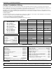
System Supervision Features
The PC1616/PC1832/PC1864 continuously monitors a number of pos-
sible trouble conditions and provides audible and visual indication at the
keypad. Multiple signals are indicated using scroll buttons on the LCD
keypads (no priority assigned) or by different lights on the LED’s key-
pads. Trouble Conditions include:
Additional Features
• Automatic inhibit (swinger shutdown) for Alarm, Tamper, Trouble
signals after 3 occurrences in a given set period (see section
[377]), Opt [1] alarms, [2] tampers, [3] troubles.
• Programmable keypad lockout option (see section [012])
• 500 Event Buffer, date and time stamped
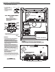
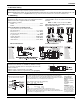
Enclosures
The PC1616/PC1832/PC1864 main board can be installed in the metal
enclosures listed below: Tamper protection switches can be installed on
all enclosures, including door opening protection and/or removal from
the mounting position. Doors can be secured using screws or keylock.
• Model PC5003C (removable door) made of 22Ga steel, painted,
dimensions: 248mm(L) x 298mm(W) x 76mm(H), weight: 1500g.
• Model Power UC1 made of 18Ga steel, painted, dimensions:
315mm(L) x 319mm(W) x 100mm(H), weight: 3150g.
• AC Power Failure
• Trouble by Zone
• Fire Trouble
• Telephone Line Trouble
• Low Battery Condition
• Bell Output Trouble
•RF Jam
• Loss of Internal Clock
• AUX Power Supply Fault
• Tamper by Zone
• Failure to Communicate
• Module Fault (Supervisory
or Tamper)