
Installation guide

Section 5 – Programming Descriptions
23
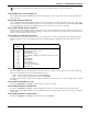
Section [402] Downloading Computer Phone Number
The Downloading Computer Telephone Number is used for Call Back, User Initiated DLS and the Auto Event Buffer Upload functions.
Program the phone number as required. HEX digits can be included for special applications:
HEX [A] Not used
HEX [B] Simulates a [
] key press
HEX [C] Simulates a [#] key press
HEX [D] Additional dial tone search
HEX [E] 2-second pause
HEX [F] End of phone number marker
Section [403] Downloading Access Code
Program the 6-digit Downloading Access Code. Upon connection, the system will only connect to the downloading computer if the
Downloading Access Code programmed matches the Downloading Access Code programmed in the computer file.
Section [404] Panel Identification Code
Program the 6-digit Panel Identification Code. This code is used by the downloading computer to verify the correct account is calling back
(Call Back feature) or to identify which customer account file should be used (User Initiated DLS and Auto Event Buffer Upload features).
Section [405] Double-Call Timer
Program the maximum time, in seconds, between calls when connecting to panel using the double call feature. Valid entries are [000] to
[255].
Section [406] Number of Rings to Answer On
Program the number of consecutive rings the panel must detect to answer for downloading. Valid entries are [000] to [010].
Section [499] PC-Link Communications
Enter the following command to initiate downloading via PC-Link – Section [499] [Installer Code] [499]. Plugging in the PC-Link connec-
tor will automatically initiate the connection if DLS is initiated before connecting the PC-Link Header.
Section [501] to [514] Programmable Output Attributes
These Sections are used to customize the operation of the PGM outputs (Section [501] for PGM 1, Section [502] for PGM 2 etc.). The avail-
able options depend on which PGM output type is programmed.
When the PGM Output Options (Section [009] to [011]) are programmed, the system will change the PGM Attributes to the default settings.
The PGM Attributes will default if a new PGM output option is programmed.
PGM Output Option [01], [03] to [08], [11] to [22], [25], [26], [28], [33]
,[34]
PGM Output Option [03], [19] to [22]
PGM Output Option [09]
[5] ON: the system attempts to call the downloading computer after transmitting a Event Buffer 75% Full event to the central station. OFF: the
system does NOT call the downloading computer after transmitting this event.
[6]-[8] For Future Use
Option Description
[3] ON: the PGM output will operate normally (switch to ground when activated). OFF: the PGM output will be normally ground and switch
to open collector (open circuit) when activated.
Option Description
[4] ON: the PGM output will activate for the duration of the PGM Output Timer when the [][7][x] command is performed.
OFF: the PGM output will latch until the [][7][x] command is performed again.
[5] ON: a valid user code must be entered after the [][7][x] command. OFF: user code is not required.
Option Description
[1] ON: PGM output activates if a Service Required trouble condition is present.
[2] ON: PGM output activates if an AC trouble condition is present.