
User guide


OPERATION MANUAL
3
20 SERIES GRAPHIC EQUALIZERS
2215-dualchannel15bandgraphicequalizer
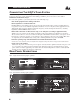
Input Gain Control: Thiscontrolsetsthesignalleveltotheequalizer.Itiscapableof-12dBto+12dBofgain.Its
effectisapparentbyviewingtheOUTPUTLEVELBARGRAPH.
EQ Bypass: Thisswitchremovesthegraphicequalizersectionfromthesignalpath.(SeeBlockdiagramonPage
32.)TheBYPASSswitchdoesnot,however,affecttheINPUTGAIN,orLOWCUTfilters.
EQ Bypass LED:ThisredLEDlightswhentheEQisinbypassmode.Notethatbypassmodeonlyeffectsthe
graphic equalizer section of the 20 Series EQs. TheINPUTGAIN and and LOWCUT controls remain unaffected
when the EQ is bypassed.
Boost/Cut Range Selection Switch and LEDs: Thisswitchselectswhichofthetwoboost/cutrangestheequalizer
willuse,either±6dBor±15dB.TheredLEDlightswhenthe±15dBrangeisselected,andtheyellowLEDlights
whenthe±6dBrangeisselected.NotethattheBOOST/CUTswitchisslightlyrecessed.Thisistopreventacciden-
talactivationoftheswitch,possiblycausingdamagetoothersoundsystemcomponents.
Output Level Bar Graph: ThesefourLEDsindicateoutputleveloftheequalizer.TheredLEDis3dBbelowclip-
pingandismarkedas+18dBu.Itmonitorsthelevelattheoutputoftheequalizerafterallotherprocessing,includ-
ing the limiter.
Clip LED: ThisLEDlightswheneveranyinternalsignallevelreaches3dBbelowclippingwhichmayoccurwhen
anyofthefollowinghappen:1)theinputsignalis“hotter”than+22dBu,2)excessivegainisappliedbytheinput
gaincontrol,or3)excessiveboostisappliedusingthefrequencysliders.
Gain Reduction Meter: ThesefourLEDsindicatetheamountofgainreductionbeinginducedbythesettingofthe
PeakPlus™LIMITERTHRESHOLDcontrol as the signal level from the graphic EQ section exceeds this limiter
threshold setting.
PeakPlus™ Limiter Threshold Control:ThiscontrolengagesthePeakPlus™limiter.Itsetsthethresholdlevelat
which ∞:1gainreductionwillbegintooccur.Itsdesignisborrowedfromthepatent-pendingPeakStopPlus™
Limiterfoundonthepopulardbx1066and1046compressor/limiters.Itiscapableofarangeof0dButhrough
“OFF”(+24dBu).Whenthethresholdcontrolissetto“OFF”,thelimiteriseffectivelydisabled,andnogainreduc-
tion will occur.
dbx Type III™ Noise Reduction Switch: TheswitchengagesthedbxTypeIII™NoiseReductioncircuitwithin
the EQ.
dbx Type III™ Noise Reduction LED:TheyellowLEDlightswhenthedbxTypeIII™NoiseReductioncircuitis
activated via theNOISEREDUCTIONSwitch.
Frequency Band Slider Controls: Each one of these slider potentiometers will boost or cut at its noted frequency
by±6dBor±15dB,dependinguponthepositionoftheBOOST/CUTRANGEswitch.Whenalltheslidersarein
thecenterdetentedpositiontheoutputoftheequalizerisflat.Thefrequencybandcentersofthe2031andthe2231
aremarkedat1/3rdofanoctaveintervalsonISOstandardspacings,whilethefrequencybandcentersofthe2215
aremarkedat2/3rdsofanoctaveintervalsonISOstandardspacings.
Low Cut Enable Switch: TheLOW-CUTswitchinsertsorremovesthe18dB/octave40HzBessellow-cutfilter
fromthesignalpath.WhentheLOW-CUTswitchispushedin,theLOW-CUTfilterisINtheaudiopath.
RANGE
GAIN
REDUCTION (dB)
OUTPUT
LEVEL (dBu)
LOW
CUT
EQ
BYPASS
TYPE
III
NR
INPUT
GAIN
dB
-12
0
+12
PeakPlus
THRESHOLD
dBu
0 OFF
+20+5
+15+10
+/-6
+/-15
CLIP
1
0
-6
+6
25 40 63 100 160 250 400 16k10k6.3k4k630 1k 1.6k 2.5k
3610+18+100-10
2215
Equalizer/Limiter
with TYPE
III NR
85-XXXX-A0 2215 FRONT ART 12-16-96
0
-15
+15
RANGE
GAIN
REDUCTION (dB)
OUTPUT
LEVEL (dBu)
LOW
CUT
EQ
BYPASS
TYPE
III
NR
INPUT
GAIN
dB
-12
0
+12
PeakPlus
THRESHOLD
dBu
0 OFF
+20+5
+15+10
+/-6
+/-15
CLIP
1
0
-6
+6
25 40 63 100 160 250 400 16k10k6.3k4k630 1k 1.6k 2.5k
3610+18+100-10
0
-15
+15