
Owner's Manual


5
EN
Step 1. Connect one end of the RCA cable to the RCA output terminals at the HU and the second end to the amplifier RCA input
terminal marked with INPUT.
5/FL
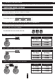
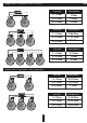
1. INPUT – signal input, RCA jack
2. CROSSOVER – HPF – high pass filter (15 Hz – 1 КHz at 12 dB/Oct)
3. CROSSOVER – LPF – low pass filter (80 Hz – 20 kHz at 12 dB/Oct)
4. POWER – LED for operation (blue)
5. CLIP – LED on the clip (yellow)
6. PROTECT – LED for operation (red)
7. SPEAKER OUTPUT – speaker terminal connections
8. +12V – power supply terminal +12 V
9. REM IN – connector of remote activation of the amplifier
10. GND – grounding supply terminal
11. GAIN – input signal level adjustment (0.2 – 6 V)
12. BASS BOOST – LEVEL – bass level adjustment (0 – 12 dB)
13. BASS BOOST – FREQUENCY – bass frequency adjustment (35 – 70 Hz)
14. REMOTE - input for connection of the bass remote control
15. OUTPUT - signal output, RCA jack
Ap pli ca ti on of c on ne cto rs a nd c o nt rol s
16. POWER – LED for operation (blue)
17. Input signal controller
18. CLIP-LED on the clip (yellow)
Re mot e co nt rol
16 17
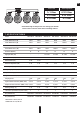
Stan dard w iri ng dia gram of mono ampl ifie r to he ad un it
1 2 3
4
5
6
7
11
12
13
1415
8 9 10
1 2 3
4
5
6
7
11
12
13
14
1. INPUT – signal input, RCA jack
2. SUBSONIC – subsonic filter (15 Hz – 50 Hz at 12 dB/Oct)
3. LPF – low pass filter (35 Hz – 180 Hz at 12 dB/Oct)
4. POWER – LED for operation (blue)
5. CLIP – LED on the clip (yellow)
6. PROTECT – LED for operation (red)
7. SPEAKER OUTPUT – speaker terminal connections
8. +12V – power supply terminal +12 V
9. REM IN – connector of remote activation of the amplifier
10. GND – grounding supply terminal
11. GAIN – input signal level adjustment (0.2 – 6 V)
12. BASS BOOST– bass level adjustment (0 – 12 dB at 45 Hz)
13. REMOTE - input for connection of the bass remote control
15. OUTPUT - signal output, RCA jack
AAP-350.1D, AAP-550.1D
AAP-800.1D, AAP-1200.1D, AAP-1600.1D, AAP-2100.1D
16 17 18