Software version 1.1 Document version 1.
1 RDNET PROTOCOL OVERVIEW ................................................................................ 2 1.1 Network description ................................................................................................ 2 1.2 Connection topology ............................................................................................... 2 2 SOFTWARE BASIC OPERATIONS ............................................................................ 3 2.1 Main View elements......................
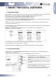
1 RDNET PROTOCOL OVERVIEW 1.1 Network description RDNet system uses a proprietary serial protocol purposely developed by dB Technologies to create a data network which can remotely manage up to 256 compatible devices (ex. dB Technologies professional speakers such as DVA T12, DVA S30N, DVA S1521N, etc.. ). The interface is managed by a PC through the DVA Network software.
2 SOFTWARE BASIC OPERATIONS 2.
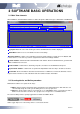
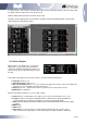
Ethernet devices are not automatically detected by software. For more details about Ethernet connection see the specific Manual section. Scan Device button: this button triggers the RDNet register procedure that scans RDNet network on each available Control and subnet, detects all the connected devices and enumerates. If the registration procedure is properly completed, the software automatically switch the mode to “Online”.
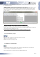
To add a speaker, first select the controller ID and the Line ID ( subnetwork number) where the device will be added, and then double click on the speaker itself. Devices will be placed near the “next device here” cursor. Normally, devices detected after a “Scan Device” operation will be automatically added in the synoptic without using the “Add Object” function. 2.5 Devices Plugins When a Device (e.g.
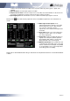
Leds become green and red according to the respective audio way status (green = signal; red = Limiting) Signal Vu-meter: show the input signal level in dBu Compression Vu-meter: show the compression level (in dB) of the internal limiters. If the device has more than one limiter this vu-meter shows the average compression value;. Input Clipping Led: This led indicator becomes red when maximum input signal is reached Clicking on the shown.
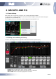
3 GROUPS AND EQ 3.1 Create a Group Each Device can be assigned to a group in order to change Eq. Delay and Gain. To add a device to a group, Right-click on the device and click ‘Assign to Group’, then select the proper group (from A to S, for example ‘A’). After assigning a device to a group, its external edge gets the group default color. 3.2 Edit Eq, Gain and Delay of a Group In order to edit Group parameters right-click on the device and click ‘Open Group Eq.’.
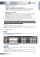
SAVE: Opens a “Save File” dialog that permits to save actual filters LOAD: Loads previously saved filters FLATTEN: sets all filters to flat DISABLE: temporarily disables filters and all group parameters SEND: sends actual filters/Volume/Delay to the speaker. In “SoundCheck” modality the button is useless since al parameters are sent automatically to devices. STORE: stores actual filters/Volume/Delay in the internal memory of the grouped devices.
4 FUNCTIONS 4.1 Functions usage In dvaNetwork functions can be applied to a collection of devices and allows the user to: Change volume and delay of a collection of devices, regardless they belong to an Eq Group. Add delay algorithm to some devices (ex. Curve algorithm that can be applied to subwoofer) Unlike Groups, more than one Function can be applied to the same device.
4.3 Functions list window Once one or more functions have been created, they can be edited and managed using the Functions list window (“Menu->System->Functions”). The view button opens the Function Edit window. The delete button simply deletes the whole function from the project. The select/Deselect toggles the selection on the synoptic from the Function’s devices. 4.4 Assign devices to an existing Function In order to assign a device to an existing function the Functions list window must be opened.
5 ADVANCED FEATURES 5.1 Parameter Protection Modality DvaNetwork allows to switch between 2 protection level: Sound Check modality: Unprotected Mode; user can edit all parameters in real time. Group Equalization, Volume and delay are changed in Live time; mute, solo and presets are sent to audio devices without confirmation. Concert modality: Protected Mode, using the “Settings” window user can select one by one which parameter will be protected in this modality.
5.4 Controllers window DvaNetwork software supports more than one Control device connected at the same time. For example you can connect a Control 2 using USB together with a Control 8 using Ethernet. Standalone devices (e.g. AC26N audio processor) can be connected to the PC directly using USB: in this case they are seen by the software as “Serial Device” and added in the controller list. The controllers window (“Menu->System->Controls list”) displays a list of detected Control units.
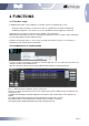
5.6 Communication Log Communication Log window (Menu-> Advanced>Communication Log) show a log of each command sent by software to any RDNet device. It is useful in detecting any failure in the Net. Every Command “Cmd” is identified by an ID number and the column “State” indicates the outcome of the command. If an error occurs the “State” field displays “TIMEOUT” or “ERROR” and the user can investigate which device generated the error by consulting “Controller”, “Line” and “Slave” fields. 5.
6 ETHERNET CONNECTION Control 8 can be connected to dvaNetwork software through an Ethernet connection. The simplest way to configure the connection requires the usage of an Ethernet hub with both PC and Control 8 connected. 6.1 Configure control 8 To configure Control8 for the Ethernet connection for the first time it’s necessary to connect the control to the PC through a USB cable. Open dvaNetwork software and make sure that RDNet Control8 firmware is updated to the latest available release.
15/16 Rev 1.