Software version 1.1 Document version 1.
DVA T8 and DVA T12 – Line Array Module .......................................................................................... 2 1 1.1 Compact View .................................................................................................................................... 2 1.2 Expanded View .................................................................................................................................. 2 DVA S1518N (Sub 18” Bandpass) and DVA S1521N (Sub 21” Bassreflex) ...
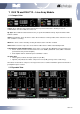
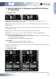
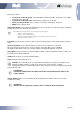
1 DVA T8 and DVA T12 – Line Array Module 1.1 Compact View Comm: Green indicates that communication between speaker and Control is working. In case of communication error the indicator becomes red. Eq. Sync: Green indicates that actual device Eq. is synchronized with the Group. Eq showed in the DVA Network software. Status: This indicator shows the device status. Green indicates normal operation; when it becomes red, an error condition is occurring.
Each panel contains: Vu-meter bar on the left (green): channel amplifier output level in dBfs (decibel full. scale, 0dBfs = maximum power delivered) ; Vu-meter bar on the right (red): channel limiter compression level in dB; amplifier temperature: indicated in °C Status indicator: green = channel is ok; Red = malfunction is detected; MUTE: single audio way mute Preset panel: Select a different audio preset (see Speaker User manual). Group panel: Assign the speaker to a Group Equalizer.
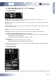
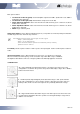
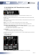
2 DVA S1518N (Sub 18” Bandpass) and DVA S1521N (Sub 21” Bassreflex) 2.1 Compact View Comm: Green indicates that communication between speaker and Control is working. In case of communication error the indicator becomes red. Eq. Sync: Green indicates that actual device Eq. is synchronized with the Group. Eq showed in the DVA Network software. Status: This indicator shows the device status. Green indicates normal operation; when it becomes red, an error condition is occurring.
Each panel contains: Vu-meter bar on the left (green): channel amplifier output level in dBfs (decibel full. scale, 0dBfs = maximum power delivered) ; Vu-meter bar on the right (red): channel limiter compression level in dB; Status (or active) indicator: green = channel is ok; Red = malfunction is detected; MUTE: single audio way mute Delay Preset panel: Select a different audio Delay preset (see Speaker User manual). Delay is indicated in mS and ranges from 0 to 4.5mS in step of 0.5mS.
3 DVA S2585N (Sub, 18” + 15” Cardiod) 3.1 Compact View Comm: Green indicates that communication between speaker and Control is working. In case of communication error the indicator becomes red. Eq. Sync: Green indicates that actual device Eq. is synchronized with the Group. Eq showed in the DVA Network software. Status: This indicator shows the device status. Green indicates normal operation; when it becomes red, an error condition is occurring.
Each panel contains: Vu-meter bar on the left (green): channel amplifier output level in dBfs (decibel full.
Group panel: Assign the speaker to a Group Equalizer. When assigned, equalization delay or volume can be modified in the Group Eq window. FW Rev: Show revision of currently loaded Firmware. Temp: indicates PSU temperature in °C. Standby: enter in standby mode to reduce internal temperature and energy consumption in long inactivity conditions. Button is usually green and becomes red in "stand-by" condition.
4 DVA S30N (Sub, 2x18” Bassreflex Horn Loaded) 4.1 Compact View Comm: Green indicates that communication between speaker and Control is working. In case of communication error the indicator becomes red. Eq. Sync: Green indicates that actual device Eq. is synchronized with the Group. Eq showed in the DVA Network software. Status: This indicator shows the device status. Green indicates normal operation; when it becomes red, an error condition is occurring.
Each panel contains: Vu-meter bar on the left (green): channel amplifier output level in dBfs (decibel full. scale, 0dBfs = maximum power delivered) ; Vu-meter bar on the right (red): channel limiter compression level in dB; Status (or active) indicator: green = channel is ok; Red = malfunction is detected; MUTE: single audio way mute Delay Preset panel: Select a different audio Delay preset (see Speaker User manual). Delay is indicated in mS and ranges from 0 to 4.5mS in step of 0.5mS.
5 AC26N – Digital Audio Processor 5.1 Compact View Comm: Green indicates that communication between speaker and Control is working. In case of communication error the indicator becomes red. Eq. Sync: Green indicates that actual device Eq. is synchronized with the Group. Eq showed in the DVA Network software. Status: This indicator shows the device status. Green indicates normal operation; when it becomes red, an error condition is occurring.
Digital Out Source This option allows to select the audio source that will be forwarded to the connector AES/EBU OUT (digital output) Analog In: Audio signals sourced from analog inputs Digital In: Audio signals sourced from digital inputs Output 1-2: Audio signals sourced from outputs 1 and 2 Output 3-4: Audio signals sourced from outputs 3 and 4 Output 5-6: Audio signals sourced from outputs 5 and 6 Input A-B link It allows to configure the inputs in stereo and joined modes, so that all the filt
5.4 PEQ Panel PEQ panel allows to equalize each single Input or Output channel, correcting one or more frequencies that have to be reduced or increased. The graphs shows a red line that represent the resultant of all activated filters. Each single filter Frequency response will be showed in white and will become Green when the corresponding filter is selected. Filter parameters can be edited by moving the round icon on the graph or analytically by inserting the data in the option boxes.
5.5 Compressor Panel Compressor panel shows the compression status for the corresponding audio channel. The compression diagram is in green colour. The configuration can be performed on the graph, by moving the circle with the relevant letter or analytically by inserting the data in the option boxes, or else by moving sliders. Threshold: Identifies the threshold where the compression ratio begins. Base is 1:1 Ratio: Indicates the conversion ratio between input and output signal.
5.6 Preset Panel The Preset List shows all the presets stored on the processor. Id: It indicates the Identifier number of the preset (from 0 to 31). Name: It indicates the name of the preset DEFAULT FACTORY PRESET: this preset is “read only” and contains the factory configuration of the processor. Local Preset: It indicates that the preset was saved via the processor local user interface (LCD display and rotary knob). Date and time are not reported. User desired name (Eg.
16/17 Rev 1.