
Quick start guide

www.dbtechnologies.com info@dbtechnologies-aeb.com
DVA K5 Rev 1.2 cod. 420120232Q
First switch on for line-array setup:
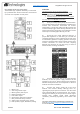
The DIGIPRO G3® amplifier of DVA K5 is controlled
by a powerful DSP. All the connections and controls
are in the rear amplifier control panel:
1 – Mains Fuse
2 – Auto-range mains input
3 – Mains (power) link output
4 – Balanced audio input
5 – Link audio output
6 – Service data mini B-type USB port
7 – DSP preset BCD rotary switches
8 – Audio input sensitivity rotary switch
9 – LEDs (Limiter, Signal, Mute/Prot, Ready)
WARNING
The fuse is factory set for 220-240 V operation.
If it is necessary to change the fuse to 100-120V range:
1. Disconnect the speaker from any cable
2. Wait 5 minutes
3. Substitute the fuse with the correct one supplied
Use only cables with Neutrik® connectors!
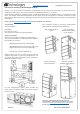
a) Once you have properly set up the desired line-
array configuration (see also the DVA K5 complete user
manual and accessories instructions for further
information), connect the audio input (4). Connect the
useful link output (5) to other DVA K5 modules, for the
audio connection of all the line-array elements. Set the
audio input sensitivity (8) of DVA K5 to 0 dB.
b) Check the rear panel reference label for a
proper DSP regulation. In this label you can find the
suggested position of rotary switches (7) for each type
of installation (Speakers Coupling positions and High
Frequency Compensation). These settings are the main
acoustic corrections to create the best coupling
between the elements of your line-array, in order to
obtain the best coverage conditions.
c) Connect the power link (3) to other DVA K5
modules, to link the power supply between all the
elements of your array. Please note that the maximum
linkable rated power and current depends on the first
module connection conditions.
d) Connect the power supply (2) to the first
module. The related “Ready” LED (9) turns on,
signaling the proper power connection. Turn the audio
input sensitivity (8) to the desired level. The “Signal”
LED (9) start blinking at the presence of audio signal
(greater than -20dBu). Avoid audio distortion
conditions, potentially signaled by the “Limiter” LED
(9).
For further information, download the complete user
manual: www.dbtechnologies.com/EN/Downloads.aspx
or scan the QR code.