
Instruction manual


Appendix 1. Outline Dimension Drawings
A1 - 26
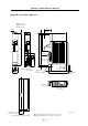
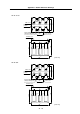
• B-AL-18.5K
PE grounding position
(with grounding mark)
55
±
1
4-8×15 slot
FG grounding
position
6-M6 scre
w
140
105
MAIN
DRIVE
L11
L12 L22 L32
L21 L31
165
±
2
125
155
Terminal cover
[Unit: mm]
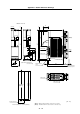
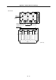
• B-AL-30K
PE grounding position
(with grounding mark)
55
±
1
4-8×15 slot
FG grounding
position
6-M6 screw
140
110
MAIN
DRIVE
L11
L12 L22 L32
L21 L31
165
±
2
125
155
Terminal cover
[Unit: mm]